Correlative Coding – Modified Duobinary Signaling

Modified Duobinary Signaling is an extension of duobinary signaling. It has the advantage of zero PSD at low frequencies (especially at DC ) that is suitable for channels with poor DC response. It correlates two symbols that are 2T time instants apart, whereas in duobinary signaling, symbols that are 1T apart are correlated.

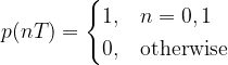
The general condition to achieve zero ISI is given by

As discussed in a previous article, in correlative coding , the requirement of zero ISI condition is relaxed as a controlled amount of ISI is introduced in the transmitted signal and is counteracted in the receiver side

In the case of modified duobinary signaling, the above equation is modified as

which states that the ISI is limited to two alternate samples. Here a controlled or “deterministic” amount of ISI is introduced and hence its effect can be removed upon signal detection at the receiver.

Modified Duobinary Signaling:

The following figure shows the modified duobinary signaling scheme (click to enlarge).

Modified DuoBinary Signaling

Encoding Process:

1) an = binary input bit; an ∈ {0,1}.
2) bn = NRZ polar output of Level converter in the precoder and is given by,

where ak is the precoded output (before level converter).

3) yn can be represented as

Note that the samples bn are uncorrelated ( i.e either +d for “1” or -d for “0” input). On the other-hand,the samples yn are correlated ( i.e. there are three possible values +2d,0,-2d depending on ak and ak-2). Meaning that the modified duobinary encoding correlates present sample ak and the previous input sample ak-2.

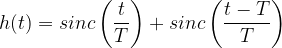
4) From the diagram,impulse response of the modified duobinary encoder is computed as

Decoding Process:

5) The receiver consists of a modified duobinary decoder and a postcoder (inverse of precoder). The decoder implements the following equation (which can be deduced from the equation given under step 3 (see above))

This equation indicates that the decoding process is prone to error propagation as the estimate of present sample relies on the estimate of previous sample. This error propagation is avoided by using a precoder before modified-duobinary encoder at the transmitter and a postcoder after the modified-duobinary decoder. The precoder ties the present sample and the sample that precedes the previous sample ( correlates these two samples) and the postcoder does the reverse process.

6) The entire process of modified-duobinary decoding and the postcoding can be combined together as one algorithm. The following decision rule is used for detecting the original modified-duobinary signal samples {an} from {yn}

Matlab code:

Check this book for full Matlab code.
Wireless Communication Systems in Matlab – by Mathuranathan Viswanathan

Simulation Results:

To know more on the simulation and results – visit this page – “Partial response signalling schemes – impulse and frequency responses”

Impulse response and frequency response of various Partial response (PR) signaling schemes

Rate this post: Note: There is a rating embedded within this post, please visit this post to rate it.

See also :

[1] Correlative Coding – Duobinary Signaling
[2] Introduction to Inter Symbol Interference

Recommended Books

Correlative coding – Duobinary Signaling

The condition for zero ISI (Inter Symbol Interference) is

which states that when sampling a particular symbol (at time instant nT=0), the effect of all other symbols on the current sampled symbol is zero.

As discussed in the previous article, one of the practical ways to mitigate ISI is to use partial response signaling technique ( otherwise called as “correlative coding”). In partial response signaling, the requirement of zero ISI condition is relaxed as a controlled amount of ISI is introduced in the transmitted signal and is counteracted in the receiver side.

By relaxing the zero ISI condition, the above equation can be modified as,

which states that the ISI is limited to two adjacent samples. Here we introduce a controlled or “deterministic” amount of ISI and hence its effect can be removed upon signal detection at the receiver.

Duobinary Signaling:

The following figure shows the duobinary signaling scheme.

Figure 1: DuoBinary signaling scheme

Encoding Process:

1) an = binary input bit; an ∈ {0,1}.
2) bn = NRZ polar output of Level converter in the precoder and is given by,

3) yn can be represented as

Note that the samples bn are uncorrelated ( i.e either +d for “1” or -d for “0” input). On the other-hand, the samples yn are correlated ( i.e. there are three possible values +2d,0,-2d depending on an and an-1). Meaning that the duobinary encoding correlates present sample an and the previous input sample an-1.

4) From the diagram,impulse response of the duobinary encoder is computed as

Decoding Process:

5) The receiver consists of a duobinary decoder and a postcoder (inverse of precoder).The duobinary decoder implements the following equation (which can be deduced from the equation given under step 3 (see above))

This equation indicates that the decoding process is prone to error propagation as the estimate of present sample relies on the estimate of previous sample. This error propagation is avoided by using a precoder before duobinary encoder at the transmitter and a postcoder after the duobinary decoder. The precoder ties the present sample and previous sample ( correlates these two samples) and the postcoder does the reverse process.

6) The entire process of duobinary decoding and the postcoding can be combined together as one algorithm. The following decision rule is used for detecting the original duobinary signal samples {an} from {yn}

Matlab Code:

Check this book for full Matlab code and simulation results.
Wireless Communication Systems in Matlab – by Mathuranathan Viswanathan

Simulation and results

To know more on the simulation and results – visit this page – “Partial response signalling schemes – impulse and frequency responses”

Impulse response and frequency response of various Partial response (PR) signaling schemes

Rate this article: Note: There is a rating embedded within this post, please visit this post to rate it.

See also :

[1] Correlative Coding – Modified Duobinary Signaling
[2] Derivation of expression for a Gaussian Filter with 3 dB bandwidth
[3] Nyquist and Shannon Theorem
[4] Correlative coding – Duobinary Signaling
[5] Square Root Raised Cosine Filter (Matched/split filter implementation)
[6] Introduction to Inter Symbol Interference

External Resources:

[1] The care and feeding of digital, pulse-shaping filters – By Ken Gentile↗
[2] Inter Symbol Interference and Root Raised Cosine Filtering – Complex2real↗