GMSK implementation and simulation – part 1

What’s the need for GMSK

Minimum shift keying (MSK) is a special case of binary CPFSK with modulation index . It has features such as constant envelope, compact spectrum and good error rate performance. The fundamental problem with MSK is that the spectrum is not compact enough to satisfy the stringent requirements with respect to out-of-band radiation for technologies like GSM and DECT standard. These technologies have very high data rates approaching the RF channel bandwidth. A plot of MSK spectrum (Figure 1) will reveal that the sidelobes with significant energy, extend well beyond the transmission data rate. This is problematic, since it causes severe out-of-band interference in systems with closely spaced adjacent channels.

Minimum shift keying (MSK) is a special case of binary CPFSK with modulation index . It has features such as constant envelope, compact spectrum and good error rate performance. The fundamental problem with MSK is that the spectrum is not compact enough to satisfy the stringent requirements with respect to out-of-band radiation for technologies like GSM and DECT standard. These technologies have very high data rates approaching the RF channel bandwidth. A plot of MSK spectrum (Figure 1) will reveal that the sidelobes with significant energy, extend well beyond the transmission data rate. This is problematic, since it causes severe out-of-band interference in systems with closely spaced adjacent channels.

This article is part of the following books
Digital Modulations using Matlab : Build Simulation Models from Scratch, ISBN: 978-1521493885
Digital Modulations using Python ISBN: 978-1712321638
All books available in ebook (PDF) and Paperback formats

PSD estimates for BPSK, QPSK and MSK signals
Figure 1: PSD estimates for BPSK, QPSK and MSK signals

To satisfy such requirements, the MSK spectrum can be easily manipulated by using a pre-modulation low pass filter (LPF). The pre-modulation LPF should have the following properties and it is found that a Gaussian LPF will satisfy all of them [1]

  • Sharp cut-off and narrow bandwidth – needed to suppress high frequency components.
  • Lower overshoot in the impulse response – providing protection against excessive instantaneous frequency deviations.
  • Preservation of filter output pulse area – thereby coherent detection can be applicable.

Pre-modulation Gaussian low pass filter

Gaussian Minimum Shift Keying (GMSK) is a modified MSK modulation technique, where the spectrum of MSK is manipulated by passing the rectangular shaped information pulses through a Gaussian LPF prior to the frequency modulation of the carrier. A typical Gaussian LPF, used in GMSK modulation standards, is defined by the zero-mean Gaussian (bell-shaped) impulse response.
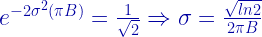
The parameter is the 3-dB bandwidth of the LPF, which is determined from a parameter called as discussed next. If the input to the filter is an isolated unit rectangular pulse (), the response of the filter will be [2]

where,

It is important to note the distinction between the two equations – (1) and (2). The equation for defines the impulse response of the LPF, whereas the equation for , also called as frequency pulse shaping function, defines the LPF’s output when the filter gets excited with a rectangular pulse. This distinction is captured in Figure 2.

Figure 2: Gaussian LPF: Relating h(t) and g(t)

The aim of using GMSK modulation is to have a controlled MSK spectrum. Effectively, a variable parameter called , the product of 3-dB bandwidth of the LPF and the desired data-rate , is often used by the designers to control the amount of spectrum efficiency required for the desired application. As a consequence, the 3-dB bandwidth of the aforementioned LPF is controlled by the design parameter. The range for the parameter is given as . When , the impulse response becomes a Dirac delta function , resulting in a transparent LPF and hence this configuration corresponds to MSK modulation.

The Matlab function to implement the Gaussian LPF’s impulse response (equation (1)), is given in the book (For Python implementation, refer this book). The Gaussian impulse response is of infinite duration and hence in digital implementations it has to be defined for a finite interval, as dictated by the function argument in the code shown next. For example, in GSM standard, is chosen as 0.3 and the time truncation is done to three bit-intervals .

It is also necessary to normalize the filter coefficients of the computed LPF as

Based on the gaussianLPF Matlab function, given in the book (For Python implementation, refer this book), we can compute and plot the impulse response and the response to an isolated unit rectangular pulse – . The resulting plot is shown in Figure 3.

Rate this article: Note: There is a rating embedded within this post, please visit this post to rate it.

References

[1] Murota, K. and Hirade, K., GMSK Modulation for Digital Mobile Radio Telephony, IEEE Transactions on Communications, vol COM-29, No. 7. pp. 1044-1050, July 1981.↗
[2] Marvin K. Simon, Bandwidth-Efficient Digital Modulation with Application to Deep Space Communications, JPL Deep Space Communications and Navigation Series,Wiley-Interscience, Hoboken, New Jersey, 2003, ISBN 0-471-44536-3,pp-57.↗

Books by the author


Wireless Communication Systems in Matlab
Second Edition(PDF)

Note: There is a rating embedded within this post, please visit this post to rate it.
Checkout Added to cart

Digital Modulations using Python
(PDF ebook)

Note: There is a rating embedded within this post, please visit this post to rate it.
Checkout Added to cart

Digital Modulations using Matlab
(PDF ebook)

Note: There is a rating embedded within this post, please visit this post to rate it.
Checkout Added to cart
Hand-picked Best books on Communication Engineering
Best books on Signal Processing

Topics in this chapter

Digital Modulators and Demodulators - Passband Simulation Models
Introduction
Binary Phase Shift Keying (BPSK)
 □ BPSK transmitter
 □ BPSK receiver
 □ End-to-end simulation
Coherent detection of Differentially Encoded BPSK (DEBPSK)
● Differential BPSK (D-BPSK)
 □ Sub-optimum receiver for DBPSK
 □ Optimum noncoherent receiver for DBPSK
Quadrature Phase Shift Keying (QPSK)
 □ QPSK transmitter
 □ QPSK receiver
 □ Performance simulation over AWGN
● Offset QPSK (O-QPSK)
● π/p=4-DQPSK
● Continuous Phase Modulation (CPM)
 □ Motivation behind CPM
 □ Continuous Phase Frequency Shift Keying (CPFSK) modulation
 □ Minimum Shift Keying (MSK)
Investigating phase transition properties
● Power Spectral Density (PSD) plots
Gaussian Minimum Shift Keying (GMSK)
 □ Pre-modulation Gaussian Low Pass Filter
 □ Quadrature implementation of GMSK modulator
 □ GMSK spectra
 □ GMSK demodulator
 □ Performance
● Frequency Shift Keying (FSK)
 □ Binary-FSK (BFSK)
 □ Orthogonality condition for non-coherent BFSK detection
 □ Orthogonality condition for coherent BFSK
 □ Modulator
 □ Coherent Demodulator
 □ Non-coherent Demodulator
 □ Performance simulation
 □ Power spectral density

Derivation of expression for a Gaussian Filter with 3 dB bandwidth

Note: There is a rating embedded within this post, please visit this post to rate it.
In GMSK modulation (used in GSM and DECT standard), a GMSK signal is generated by shaping the information bits in NRZ format through a Gaussian Filter. The filtered pulses are then frequency modulated to yield the GMSK signal. GMSK modulation is quite insensitive to non-linearities of power amplifier and is robust to fading effects. But it has a moderate spectral efficiency.

An expression for the Gaussian Filter with 3dB Bandwidth is derived here.

The requirements for a gaussian filter used for GMSK modulation in GSM/DECT standard  are as follows,

Now the challenge is to design a Gaussian Filter fG(t) that satifies the 3dB bandwidth requirement i.e. in the frequency domain at some frequency f=B, the filter should posses -3dB gain ( in otherwords => half power point located at f=B)

The probability density function for a Gaussian Distribution with mean=0 and standard deviation=σ  is given by

The expression for the required Gaussian Filter can be obtained by choosing the variance of the above mentioned distribution so that the Fourier Transform of the above mentioned expression has a -3dB power gain at f=B.

The fourier transform of the above mentioned expression is

Setting f=B,

See also :

[1] Correlative Coding – Modified Duobinary Signaling
[2] Correlative Coding – Duobinary signaling
[3] Nyquist and Shannon Theorem
[4] Correlative coding – Duobinary Signaling
[5] Square Root Raised Cosine Filter (Matched/split filter implementation)
[6] Introduction to Inter Symbol Interference

External Resources:

[1] The care and feeding of digital, pulse-shaping filters – By Ken Gentile
[2] Inter Symbol Interference and Root Raised Cosine Filtering – Complex2real

Recommended Books