In coherent detection, the receiver derives its demodulation frequency and phase references using a carrier synchronization loop. Such synchronization circuits may introduce phase ambiguity $latex \phi = \hat{\theta}-\theta $ in the detected phase, which could lead to erroneous decisions in the demodulated bits. For example, Costas loop exhibits phase ambiguity of integral multiples of $latex \pi$ radians at the lock-in points. As a consequence, the carrier recovery may lock in $latex \pi$ radians out-of-phase thereby leading to a situation where all the detected bits are completely inverted when compared to the bits during perfect carrier synchronization. Phase ambiguity can be efficiently combated by applying differential encoding at the BPSK modulator input (Figure 1) and by performing differential decoding at the output of the coherent demodulator at the receiver side (Figure 2).
[table “38” not found /]
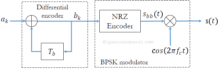
In ordinary BPSK transmission, the information is encoded as absolute phases: $latex \theta=0^{\circ}$ for binary 1 and $latex \theta=180^{\circ}$ for binary 0. With differential encoding, the information is encoded as the phase difference between two successive samples. Assuming $latex a[k]$ is the message bit intended for transmission, the differential encoded output is given as
$latex b[k] = b[k-1] \oplus a[k] \;\;\;\;\;\; (modulo-2) \;\;\;\;\;\; (1) &s=2$
The differentially encoded bits are then BPSK modulated and transmitted. On the receiver side, the BPSK sequence is coherently detected and then decoded using a differential decoder. The differential decoding is mathematically represented as
$latex a[k] = b[k] \oplus b[k-1] \;\;\;\;\;\; (modulo-2) \;\;\;\;\;\; (2) &s=2$
This method can deal with the $latex 180^{\circ}$ phase ambiguity introduced by synchronization circuits. However, it suffers from performance penalty due to the fact that the differential decoding produces wrong bits when: a) the preceding bit is in error and the present bit is not in error , or b) when the preceding bit is not in error and the present bit is in error. After differential decoding, the average bit error rate of coherently detected BPSK over AWGN channel is given by
$latex P_b = erfc \left(\sqrt{\frac{E_b}{N_0}} \right) \left[ 1-\frac{1}{2} erfc \left( \sqrt{\frac{E_b}{N_0}} \right) \right] \;\; (3) &s=2$

Following is the Matlab implementation of the waveform simulation model for the method discussed above. Both the differential encoding and differential decoding blocks, illustrated in Figures 1 and 2, are linear time-invariant filters. The differential encoder is realized using IIR type digital filter and the differential decoder is realized as FIR filter.
File 1: dbpsk_coherent_detection.m: Coherent detection of D-BPSK over AWGN channel
Refer Digital Modulations using Matlab : Build Simulation Models from Scratch for full Matlab code. Refer Digital Modulations using Python for full Python code.
Figure 3 shows the simulated BER points together with the theoretical BER curves for differentially encoded BPSK and the conventional coherently detected BPSK system over AWGN channel.

Rate this article: [ratings]
Topics in this chapter
[table “29” not found /]Books by the author
[table “23” not found /]