Key focus: As per Nyquist ISI criterion, to achieve zero intersymbol interference (ISI), samples must have only one non-zero value at each sampling instant.
Consider an equivalent baseband communication system model with baud rate ( is the symbol period) shown in Figure 1, where the transmitter, channel and the receiver are represented as band-limited filters.
Figure 1: An equivalent communication system model
The entire combination of filters can be represented as the following Fourier transform pair
Given the noise term , the output of the receiving filter is given as
where, is the overall impulse response of the system due to an impulse at its input. Normalizing (where the signal of interest lies), at the symbol sampling instants ,
where, is the symbol of interest at sampling instant, is the noise at that sampling instant and the remaining terms are contributions from other symbols – representing intersymbol interference. For nullifying the ISI terms, with an impulse of unit value applied at to the combined filters , the samples of the at the output of the filter combination should be 1 at the sampling instant and zero at all other sampling instants . This is called Nyquist criterion for zero ISI. In frequency domain, the frequency-shifted replicas of the overall system transfer function should add up to a constant value.
It can be readily seen that, in time domain, the simplest signal that naturally avoids ISI is the rectangular pulse of width but it consumes infinite bandwidth. On the other hand, the signal that avoids ISI with the least amount of bandwidth is a sinc pulse of bandwidth . The next section walks thorough the various choices of pulse shapes that are available for avoiding or mitigating ISI.
Rate this article: Note: There is a rating embedded within this post, please visit this post to rate it.
Key focus: Inter-symbol interference: symbols sent through a dispersive channel, arrive at different time intervals and interfere due to non-constant group delay.
Introduction
Communication systems have progressed from analog to digital implementation due to the latter’s advantages of bandwidth efficiency and exceptional immunity to noise. The greatest challenge to a communication systems engineer lies in designing a system that strikes a trade-off between the physical limitations of a given communication system, the need for higher capacity and the available resources such as bandwidth usage and power. Modern communication systems should operate in a very limited radio spectrum with minimized interference to other systems.
Numerous standardization committees define spectral masks for specific applications with the aim of reducing the interference to other systems by limiting the out-of-band radiations. Spectral masks are implemented by pulse shaping filters. Pulse shaping should contain the transmit signal within the specified band while minimizing the probability of errors at the receiver. On the other hand, pulse shaping causes inter-symbol interference (ISI) that degrades the detection process and therefore brings down the error performance of the whole system.
Most of the communication channels (data storage devices, optical, wireless channels etc…) can be considered as band-limited linear filters. Thus these channels can be modeled as having the following frequency response
where, is amplitude response and is the phase response of the channel. The envelope or group delay for the given filter model is defined as,
A channel is considered non-distorting (within the given bandwidth occupied by the transmitted signal), when the amplitude response is constant and the phase response is a linear function of frequency. In other words, the channel has a constant group delay.
Amplitude distortion occurs when the amplitude response is no longer a constant and delay distortion or phase distortion occurs when the phase response is not a linear function of frequency (that is, the envelope or group delay is not a constant). Channels with delay distortion are termed as dispersive channels.
When a succession of pulses are transferred through a dispersive channel, the pulses may arrive at different time intervals the output of the channel due to non-constant group delay. As a result, the transmitted pulses may interfere with each other, rendering them completely indistinguishable at the receiver. This phenomenon is called inter-symbol interference (ISI). Dispersive effects are particularly relevant in high data rate communication systems. Delay dispersion can also manifest in time-variant multipath channels, since the copies of signals traveling via each propagating path may arrive at different times at the receiver thereby giving rise to ISI. Following are the major approaches to deal with ISI.
Partial response signaling: Introduce controlled amount of ISI in the transmit side and prepare to deal with it at the receiver
Design algorithms to counter ISI: Learn to live with the presence of ISI and design robust algorithms at the receiver – Viterbi algorithm↗ (maximum likelihood sequence estimation), equalizer etc.,
Demo in Matlab and Python
Consider a band-limited channel, modeled as an ideal brickwall low pass filter. The cut-off frequency of the low pass channel is rad/sample. An unit impulse is sent through the channel. As expected, we get a sinc pulse at the channel output (Figure 1, plots in the first row).
Next, a series of pulses with values [1,-1,1] are sent through the band-limited channel, at low data rate. Low data rate implies, there is sufficient pauses between the transmission of each value. The output of the channel shows clearly distinguishable peaks. As a consequence, the receiver can distinguish the values by simply sampling at the signal peaks (sampling is done at regular interval). This scenario is illustrated by Figure 1 row 2 plots.
Finally, plots in the row 3 of Figure 1 is for high speed data transmission, where the values [1,-1,1] are transmitted consecutively without any pause in between them. Due to the band-limited nature of the dispersive channel, the sinc pulses interfere with each other, thereby producing a smeared output. Now, the receiver cannot discern the values from the received signal. This phenomenon is called ‘inter-symbol interference’ (to be exact – inter-bit interference in this case 🙂 ).
Modified Duobinary Signaling is an extension of duobinary signaling. It has the advantage of zero PSD at low frequencies (especially at DC ) that is suitable for channels with poor DC response. It correlates two symbols that are 2T time instants apart, whereas in duobinary signaling, symbols that are 1T apart are correlated.
The general condition to achieve zero ISI is given by
As discussed in a previous article, in correlative coding , the requirement of zero ISI condition is relaxed as a controlled amount of ISI is introduced in the transmitted signal and is counteracted in the receiver side
In the case of modified duobinary signaling, the above equation is modified as
which states that the ISI is limited to two alternate samples. Here a controlled or “deterministic” amount of ISI is introduced and hence its effect can be removed upon signal detection at the receiver.
Modified Duobinary Signaling:
The following figure shows the modified duobinary signaling scheme (click to enlarge).
Modified DuoBinary Signaling
Encoding Process:
1) an = binary input bit; an ∈ {0,1}.
2) bn = NRZ polar output of Level converter in the precoder and is given by,
where ak is the precoded output (before level converter).
3) yn can be represented as
Note that the samples bn are uncorrelated ( i.e either +d for “1” or -d for “0” input). On the other-hand,the samples yn are correlated ( i.e. there are three possible values +2d,0,-2d depending on ak and ak-2). Meaning that the modified duobinary encoding correlates present sample ak and the previous input sample ak-2.
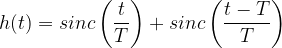
4) From the diagram,impulse response of the modified duobinary encoder is computed as
Decoding Process:
5) The receiver consists of a modified duobinary decoder and a postcoder (inverse of precoder). The decoder implements the following equation (which can be deduced from the equation given under step 3 (see above))
This equation indicates that the decoding process is prone to error propagation as the estimate of present sample relies on the estimate of previous sample. This error propagation is avoided by using a precoder before modified-duobinary encoder at the transmitter and a postcoder after the modified-duobinary decoder. The precoder ties the present sample and the sample that precedes the previous sample ( correlates these two samples) and the postcoder does the reverse process.
6) The entire process of modified-duobinary decoding and the postcoding can be combined together as one algorithm. The following decision rule is used for detecting the original modified-duobinary signal samples {an} from {yn}
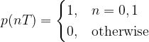
The condition for zero ISI (Inter Symbol Interference) is
which states that when sampling a particular symbol (at time instant nT=0), the effect of all other symbols on the current sampled symbol is zero.
As discussed in the previous article, one of the practical ways to mitigate ISI is to use partial response signaling technique ( otherwise called as “correlative coding”). In partial response signaling, the requirement of zero ISI condition is relaxed as a controlled amount of ISI is introduced in the transmitted signal and is counteracted in the receiver side.
By relaxing the zero ISI condition, the above equation can be modified as,
which states that the ISI is limited to two adjacent samples. Here we introduce a controlled or “deterministic” amount of ISI and hence its effect can be removed upon signal detection at the receiver.
Duobinary Signaling:
The following figure shows the duobinary signaling scheme.
Figure 1: DuoBinary signaling scheme
Encoding Process:
1) an = binary input bit; an ∈ {0,1}. 2) bn = NRZ polar output of Level converter in the precoder and is given by,
3) yn can be represented as
Note that the samples bn are uncorrelated ( i.e either +d for “1” or -d for “0” input). On the other-hand, the samples yn are correlated ( i.e. there are three possible values +2d,0,-2d depending on an and an-1). Meaning that the duobinary encoding correlates present sample an and the previous input sample an-1.
4) From the diagram,impulse response of the duobinary encoder is computed as
Decoding Process:
5) The receiver consists of a duobinary decoder and a postcoder (inverse of precoder).The duobinary decoder implements the following equation (which can be deduced from the equation given under step 3 (see above))
This equation indicates that the decoding process is prone to error propagation as the estimate of present sample relies on the estimate of previous sample. This error propagation is avoided by using a precoder before duobinary encoder at the transmitter and a postcoder after the duobinary decoder. The precoder ties the present sample and previous sample ( correlates these two samples) and the postcoder does the reverse process.
6) The entire process of duobinary decoding and the postcoding can be combined together as one algorithm. The following decision rule is used for detecting the original duobinary signal samples {an} from {yn}
This website uses cookies to improve your experience while you navigate through the website. Out of these, the cookies that are categorized as necessary are stored on your browser as they are essential for the working of basic functionalities of the website. We also use third-party cookies that help us analyze and understand how you use this website. These cookies will be stored in your browser only with your consent. You also have the option to opt-out of these cookies. But opting out of some of these cookies may affect your browsing experience.
Necessary cookies are absolutely essential for the website to function properly. These cookies ensure basic functionalities and security features of the website, anonymously.
Cookie
Duration
Description
cookielawinfo-checbox-analytics
11 months
This cookie is set by GDPR Cookie Consent plugin. The cookie is used to store the user consent for the cookies in the category "Analytics".
cookielawinfo-checbox-analytics
11 months
This cookie is set by GDPR Cookie Consent plugin. The cookie is used to store the user consent for the cookies in the category "Analytics".
cookielawinfo-checbox-functional
11 months
The cookie is set by GDPR cookie consent to record the user consent for the cookies in the category "Functional".
cookielawinfo-checbox-functional
11 months
The cookie is set by GDPR cookie consent to record the user consent for the cookies in the category "Functional".
cookielawinfo-checbox-others
11 months
This cookie is set by GDPR Cookie Consent plugin. The cookie is used to store the user consent for the cookies in the category "Other.
cookielawinfo-checbox-others
11 months
This cookie is set by GDPR Cookie Consent plugin. The cookie is used to store the user consent for the cookies in the category "Other.
cookielawinfo-checkbox-necessary
11 months
This cookie is set by GDPR Cookie Consent plugin. The cookies is used to store the user consent for the cookies in the category "Necessary".
cookielawinfo-checkbox-performance
11 months
This cookie is set by GDPR Cookie Consent plugin. The cookie is used to store the user consent for the cookies in the category "Performance".
viewed_cookie_policy
11 months
The cookie is set by the GDPR Cookie Consent plugin and is used to store whether or not user has consented to the use of cookies. It does not store any personal data.
Functional cookies help to perform certain functionalities like sharing the content of the website on social media platforms, collect feedbacks, and other third-party features.
Performance cookies are used to understand and analyze the key performance indexes of the website which helps in delivering a better user experience for the visitors.
Analytical cookies are used to understand how visitors interact with the website. These cookies help provide information on metrics the number of visitors, bounce rate, traffic source, etc.