Key focus: Sinc pulse shaping of transmitted bits, offers minimum bandwidth and avoids intersymbol interference. Discuss its practical considerations & simulation.
Sinc pulse shaping
As suggested in the earlier post, the pulse shape that avoids ISI with the least amount of bandwidth is a sinc pulse of bandwidth $latex F_{sym}/2$. Here, $latex F_{sym}=1/T_{sym}$ is the baud rate of the system also called symbol rate. A sinc pulse described as time and frequency domain dual is given below

Following Matlab codes generate a sinc pulse with $latex T_{sym}=1s$ and plot the time-domain/frequency-domain response (Figure 1). From the time-domain plot, the value of the sinc pulse hits zero at integral multiple sampling instants $latex kT_{sym}=k \times 1 $ seconds except at $latex t=0$ where it peaks to the maximum value. Thus the sinc pulse satisfies the Nyquist criterion for zero ISI.
This article is part of the book Wireless Communication Systems in Matlab, ISBN: 978-1720114352 available in ebook (PDF) format (click here) and Paperback (hardcopy) format (click here).
Program 1: sincFunction.m: Function for generating sinc pulse
Program 2: Sinc pulse and its manifestation in frequency domain
Tsym=1; %Symbol duration
L=16; %oversampling rate, each symbol contains L samples
Nsym = 80; %filter span in symbol duration
Fs=L/Tsym; %sampling frequency
[p,t]=sincFunction(L,Nsym); %Sinc Pulse
subplot(1,2,1); t=t*Tsym; plot(t,p); title('Sinc pulse');
[fftVals,freqVals]=freqDomainView(p,Fs,'double'); %See Chapter 1
subplot(1,2,2);
plot(freqVals,abs(fftVals)/abs(fftVals(length(fftVals)/2+1)));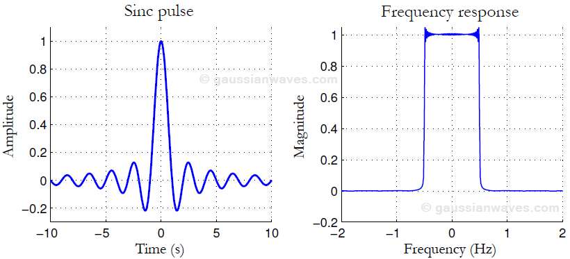
The main drawback of the sinc pulse is that it decays too slowly at the rate of $latex 1/|t|$ as $latex t \rightarrow \infty$. This implies that the samples that are far apart can cause intersymbol interference in the event of modest clock synchronization errors. A sinc pulse is of infinite duration and for practical implementations, it has to be truncated to finite length $latex kT_{sym}$ for some integer $latex k$. This leads to problems in frequency domain as explained next.

Figure 2 shows the one-sided frequency response of the sinc pulse that is truncated to various lengths. It is evident that the truncation of sinc pulse in time domain to $latex \pm kT_{sym}$ leads to sidelobes in the frequency domain and the sidelobes become wider for decreasing values of $latex k$. This effect is closely related to Gibbs phenomenon – the ringing artifact due to approximation of discontinuities by spectral methods. As a result, no matter how large the value of $latex k$ is chosen, the first sidelobe is always only $latex \sim 21 \; dB$ down from the main lobe. Also, the sinc pulse is very sensitive to the timing jitters at the receiver. These problems can be addressed when the transition band in the frequency domain is made less abrupt.
Rate this article: [ratings]
Books by the author
[table “23” not found /]