Rectangular pulse shaping – simulation model

Key focus: Rectangular pulse shaping with abrupt transitions eliminates intersymbol interference, but it has infinitely extending frequency response. Simulation discussed.

Rectangular pulse

A rectangular pulse with abrupt transitions is a natural choice for eliminating ISI. If an information sequence is shaped as rectangular pulses, at the symbol sampling instants, the interference due to other symbols are always zero. Easier to implement in hardware or software, a rectangular pulse of duration can be generated by the following function

The complete set of Matlab codes to generate a rectangular pulse and to plot the time-domain view and the frequency response is available in the book Wireless Communication Systems in Matlab.

This article is part of the book Wireless Communication Systems in Matlab, ISBN: 978-1720114352 available in ebook (PDF) format (click here) and Paperback (hardcopy) format (click here).

Program 1: rectFunction.m: Function for generating a rectangular pulse

function [p,t,filtDelay]=rectFunction(L,Nsym)
%Function for generating rectangular pulse for the given inputs
%L - oversampling factor (number of samples per symbol)
%Nsym - filter span in symbol durations
%Returns the output pulse p(t) that spans the discrete-time base
%-Nsym:1/L:Nsym. Also returns the filter delay.

Tsym=1;
t=-(Nsym/2):1/L:(Nsym/2); %unit symbol duration time-base
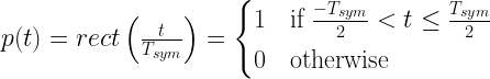
p=(t > -Tsym/2) .* (t <= Tsym/2);%rectangular pulse

%FIR filter delay = (N-1)/2, N=length of the filter
filtDelay = (length(p)-1)/2; %FIR filter delay end

Program 2: test rectPulse.m: Rectangular pulse and its manifestation in frequency domain

Matlab code for Program 2 is available is available in the book Wireless Communication Systems in Matlab.

Rectangular pulse and its manifestation in frequency domain
Figure 1: Rectangular pulse and its manifestation in frequency domain

As shown in Figure 1, the rectangular pulse in the time-domain manifests as a sinc function that extends infinitely on either side of the frequency spectrum (though only a portion of the frequency response is plotted in the figure) and thus its spectrum is not band-limited. When the infinitely extending frequency response is stuffed inside a band-limited channel, the truncation of the spectrum leads to energy spills in the time-domain. If we were to use sharp rectangular pulses, it needs a huge bandwidth that could violate practical design specs.

Rate this article: Note: There is a rating embedded within this post, please visit this post to rate it.

Books by the author


Wireless Communication Systems in Matlab
Second Edition(PDF)

Note: There is a rating embedded within this post, please visit this post to rate it.
Checkout Added to cart

Digital Modulations using Python
(PDF ebook)

Note: There is a rating embedded within this post, please visit this post to rate it.
Checkout Added to cart

Digital Modulations using Matlab
(PDF ebook)

Note: There is a rating embedded within this post, please visit this post to rate it.
Checkout Added to cart
Hand-picked Best books on Communication Engineering
Best books on Signal Processing

Topics in this chapter

Pulse Shaping, Matched Filtering and Partial Response Signaling
● Introduction
● Nyquist Criterion for zero ISI
● Discrete-time model for a system with pulse shaping and matched filtering
 □ Rectangular pulse shaping
 □ Sinc pulse shaping
 □ Raised-cosine pulse shaping
 □ Square-root raised-cosine pulse shaping
● Eye Diagram
● Implementing a Matched Filter system with SRRC filtering
 □ Plotting the eye diagram
 □ Performance simulation
● Partial Response Signaling Models
 □ Impulse response and frequency response of PR signaling schemes
● Precoding
 □ Implementing a modulo-M precoder
 □ Simulation and results

Discrete-time communication system model

Key focus: Baseband communication system and its equivalent DSP implementation (discrete time model) with a pulse shaping & matched filter is briefly introduced.

If a train of pulses representing an information sequence need to be sent across a band-limited dispersive channel, the bandwidth of the channel should be large enough to accommodate the entire spectrum of the signal that is being sent. If we try to stuff the signal spectrum without proper pulse shaping into a band-limited channel, the spectrum of the received signal at the receiver will be truncated by the band-limiting nature of the channel. In time-domain, the energy of one pulse may spill to the time slot allocated for one or more adjacent pulses, leading to Inter-Symbol Interference (ISI) and therefore a source of error in the receiver.

ISI can be minimized by optimal signal design and the detection of a signal with known pulse shape that is buried in noise is a well-studied problem in communication. At the receiver, optimal signal detection is performed by a matched filter whose impulse response is matched to the impulse response of the pulse shaping filter employed at the transmitter.

This article is part of the book
Wireless Communication Systems in Matlab (second edition), ISBN: 979-8648350779 available in ebook (PDF) format and Paperback (hardcopy) format.

A typical baseband communication system and its equivalent DSP implementation (discrete time model) with a matched filter is shown in Figure 1. The interpolating filter at the transmitter is implemented in DSP as a chain of upsampler and a pulse shaping function. The upsampler inserts L-1 zeros between the successive incoming data samples and the pulse shaping filter fills in the zeros generated by the upsampler by using a pulse shaping function. On the other hand, the receiver contains a downsampler that keeps every Lth sample starting from a specified offset. The factor L denotes the oversampling factor or upsampling ratio which is given as the ratio of symbol period (Tsym) and the sampling period (Ts) or equivalently, the ratio of sampling rate Fs and the symbol rate Fsym as

Figure 1: A typical baseband communication system (top) and its equivalent DSP implementation (bottom)

The interpolating filter at the transmitter is implemented in DSP as a chain of upsampler and a pulse shaping function. The upsampler inserts zeros between the successive incoming data samples and the pulse shaping filter fills in the zeros generated by the upsampler by using a pulse shaping function. On the other hand, the receiver contains a downsampler that keeps every sample starting from a specified offset. The factor denotes the oversampling factor or upsampling ratio which is given as the ratio of symbol period () and the sampling period () or equivalently, the ratio of sampling rate and the symbol rate as

The implementation of impulse response of the most widely discussed pulsing shaping functions (filters) will follow in the next series of articles, followed by an example on a complete matched filter system with square-root raised-cosine pulse shaping.

Rate this article: Note: There is a rating embedded within this post, please visit this post to rate it.

Books by the author


Wireless Communication Systems in Matlab
Second Edition(PDF)

Note: There is a rating embedded within this post, please visit this post to rate it.
Checkout Added to cart

Digital Modulations using Python
(PDF ebook)

Note: There is a rating embedded within this post, please visit this post to rate it.
Checkout Added to cart

Digital Modulations using Matlab
(PDF ebook)

Note: There is a rating embedded within this post, please visit this post to rate it.
Checkout Added to cart
Hand-picked Best books on Communication Engineering
Best books on Signal Processing

Topics in this chapter

Pulse Shaping, Matched Filtering and Partial Response Signaling
● Introduction
● Nyquist Criterion for zero ISI
● Discrete-time model for a system with pulse shaping and matched filtering
 □ Rectangular pulse shaping
 □ Sinc pulse shaping
 □ Raised-cosine pulse shaping
 □ Square-root raised-cosine pulse shaping
● Eye Diagram
● Implementing a Matched Filter system with SRRC filtering
 □ Plotting the eye diagram
 □ Performance simulation
● Partial Response Signaling Models
 □ Impulse response and frequency response of PR signaling schemes
● Precoding
 □ Implementing a modulo-M precoder
 □ Simulation and results