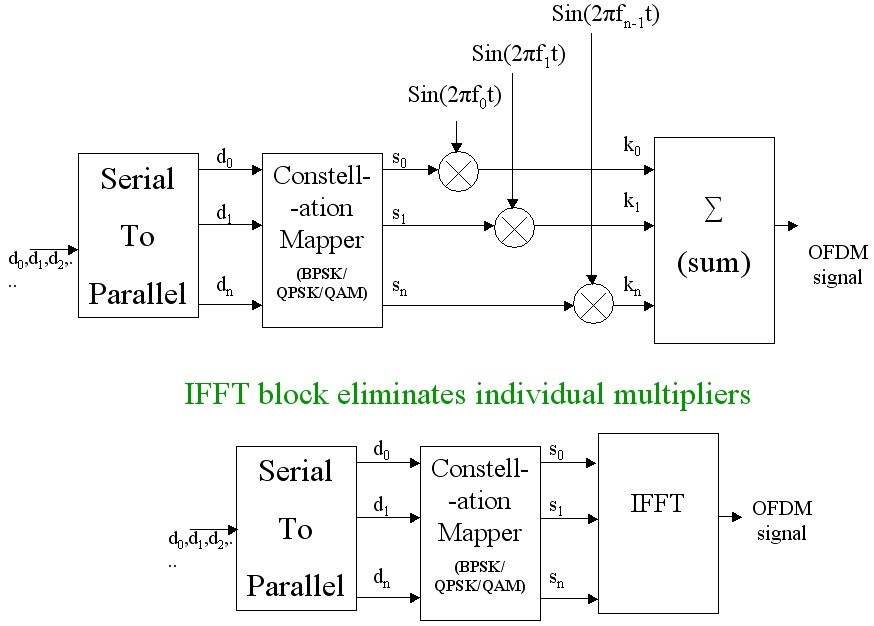
In the previous article, the architecture of an OFDM transmitter was described using sinusoidal components. Generally, an OFDM signal can be represented as
\[OFDM\; signal = c(t)=\sum_{n=0}^{N-1}s_{n}(t)sin(2\pi f_{n}t )\]\(s(t)\) = symbols mapped to chosen constellation (BPSK/QPSK/QAM etc..,)
\(f_n\) = orthogonal frequency
This equation can be thought of as an IFFT process ( Inverse Fast Fourier Transform). The Fourier transform breaks a signal into different frequency bins by multiplying the signal with a series of sinusoids. This essentially translates the signal from time domain to frequency domain. But, we always view IFFT as a conversion process from frequency domain to time domain.
FFT is represented by
\[X(k)=\sum_{n=0}^{N-1}x(n) \cdot sin \left(\frac{2\pi kn}{N} \right)+j\sum_{n=0}^{N-1}x(n) \cdot cos \left(\frac{2\pi kn}{N} \right)\] \[x(n)=\sum_{n=0}^{N-1}X(k) \cdot sin \left(\frac{2\pi kn}{N} \right)-j\sum_{n=0}^{N-1}X(k) \cdots cos \left(\frac{2\pi kn}{N} \right)\]where as its dual , IFFT is given by
The equation for FFT and IFFT differ by the co-efficients they take and the minus sign. Both equation does the same thing. They multiply the incoming signal with a series of sinusoids and separates them into bins.In fact, FFT and IFFT are dual and behaves in a similar way.IFFT and FFT blocks are interchangeable.
Since the OFDM signal ( c(t) in the equation above ) is in time domain, IFFT is the appropriate choice to use in the transmitter, which can be thought of as converting frequency domain samples to time domain samples. Well, you might ask : s(t) is not in frequency domain and they are already in time domain; so whats the need to convert it into time domain again ? The answer is IFFT/FFT equation comes handy in implementing the conversion process and we can eliminate the individual sinusoidal multipliers required in the transmitter/receiver side. The following figure illustrates, how the use of IFFT in the transmitter eliminates the need for separate sinusoidal converters. Always remember that IFFT and FFT blocks in the transmitter are interchangeable as long as their duals are used in receiver.
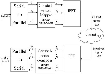
The entire architecture of a basic OFDM system with both transmitter and receiver will look like this
An OFDM system is defined by IFFT/FFT length – N ,the underlying modulation technique ( BPSK/QPSK/QAM), supported data rate, etc..,. The FFT/IFFT length N defines the number of total subcarriers present in the OFDM system. For example, an OFDM system with N=64 provides 64 subcarriers. In reality, not all the subcarriers are utilized for data transmission. Some subcarriers are reserved for pilot carriers (used for channel estimation/equalization and to combat magnitude and phase errors in the receiver) and some are left unused to act as guard band. OFDM system do not transmitany data on the subcarriers that are near the two ends of the transmission band ( Not necessarily at the ends of the bands, implementation may differ). These subcarriers are collectively called guard band. The reservation of subcarriers to guard bands helps to reduce the out of band radiation and thus eases the requirements on transmitter front-end filters.The subcarriers in the guard band are also called Null subcarriers or virtual subcarriers.
For example IEEE 802.11 standard[1] specifies the following parameters for its OFDM physical layer.
FFT/IFFT size = 64 ( implies 64 subcarriers in total = used + unused = N_{fft})
Number of data subcarriers = 48 (\( N_d\))
Number of pilot subcarriers = 4 (\(N_p\))
Derived parameters from the above specification.
Number of total USED subcarriers = 52 (\( N_u = N_d+ N_p \))
Number of total UNUSED subcarriers = 12 (\( N_{un} = N_{fft} – N_u\)).
According to the spec, these 52 used subcarriers are distributed in the following way. The 52 used subcarriers are named as 1,2,3,…,26 and -1,-2,-3,…,-26. The used subcarriers 1 to 26 are mapped to 1 to 26 of IFFT inputs and the subcarriers -1,-2,..,-26 are mapped to the IFFT inputs 38 to 63. The remaining IFFT inputs 27 to 37 and the input 0 (dc input) are set to 0 .In this manner the 12 null subcarriers are mapped to IFFT inputs.
Check this book for full Matlab code: Wireless Communication Systems in Matlab, ISBN: 978-1720114352 available in ebook (PDF) format (click here) and Paperback (hardcopy) format (click here).
Reference:
See also:
(1) Introduction to OFDM – orthogonal Frequency division multiplexing
(2) Role of Cyclic Prefix in OFDM
(3) Simulation of OFDM system in Matlab – BER Vs Eb/N0 for OFDM in AWGN channel
Hi Sai,
There is nothing special in OFDM as far as calculation of bit rate is concerned as you might think. It uses only one underlying modulation technique at one time.
So the same calculation can be applied to OFDM as well. For example, if OFDM uses QPSK as the underlying modulation technique, the bitrate calculation will be same as that of normal QPSK.
Respectd Sir,
This is Sai again. If we consider the 802.11g PHY model, modulation schemes like BPSK,QPSK,16 QAM,64QAM are all used. But the final bitrate of the 802.11g models is a single value which ranges from 2mbps to 54mbps.
As you said that the bitrate depends on the modulation scheme sselected at a particular time, we should get 4 different bitrates but that aint happening. There is only one single bitrate at the output.
http://www.mathworks.com/matlabcentral/fileexchange/38073-802-11g-wlan-phy-model — this site provides the simulink model of 802.11g PHY layer. You can clearly understand my question if you simulate that model.
Kindly help!
Thank you.
Hi Sai,
Got the context in which you are talking about… Let me go through 802.11g spec and get back to you soon.
— Updated —
I have gone through 802.11g specification and for the modulation format concerned you have to refer 802.11a specification which is available here .. http://standards.ieee.org/getieee802/download/802.11-2012.pdf
Check chapter 18 on OFDM PHY specification, sub topic – 18.3.2.3 Modulation-dependent parameters.
The supported data rates are listed here. 802.11g specification gives you several options to choose your modulation format to get desired data rate. Only one modulation format is support at one time. There is no mixing of different modulation types. IF you choose OFDM-BPSK and a 1/2 coding scheme, you get 6Mbps data rate (for 20 MHz channel spacing) – See attached image below. If you choose OFDM-QPSK with 1/2 rate coding scheme, you get 12 Mbps data rate.
Even in the simulink model that you are referring to, the modulator is initialized as follows
switch modulation
case ‘BPSK’, Nb1 = 1;
case ‘QPSK’, Nb1 = 2;
case ’16-QAM’, Nb1 = 4;
case ’64-QAM’, Nb1 = 6;
case ‘DQPSK’, Nb1 = 8;
case ‘OQPSK’, Nb1 = 16;
end
So the code essentially choose only one modulation type depending on the value of the variable – “modulation”.
Thanks a lot Sir! So the final output (bitrate-18mbps) that I am getting in the display box means that at the last time slot QPSK scheme is selected and the bit rate corresponds to that modulation scheme!
Thankyou :)!
Please do visit my blog http://www.theresplendentlife.wordpress.com.
Respected Sir, I have one more question if you don’t mind. I am currently working on the simulink model of 802.11g. I am unable to understand this block that I have attached in the comment.
http://s1355.photobucket.com/user/saikrishnaviru/media/Capture_zps114310df.jpg.html
Thankyou.
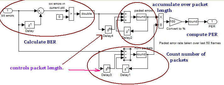
Looks like packer error rate (PER) is being calculated. The individual data bits received by the receiver are compare with the sent ones.
This gives the Bit Error Rate (BER). The delay block $latex Z^{-50} $ controls the packet length (may be in bits). The two $latex Z^{-1} $ blocks feeding backwards indicate accumulator. It accumulates the values. The top one accumulates the packet errors and the bottom one accumulate the number of packets transmitted. Dividing packet errors and number of packets transmitter will give PER.
Check the annotations on the image below
Respected Sir,
The more deeply I am studying this model the more doubts I’m getting! Kindly help me out with this one-
http://s1355.photobucket.com/user/saikrishnaviru/media/akil_zps63459fd6.jpg.html
Please explain me the use of Hermitian Transpose there and its operation.
and also this http://s1355.photobucket.com/user/saikrishnaviru/media/akil2_zps894aecb4.jpg.html?sort=3&o=0
Why are variance and snrdb being added before giving them as the input to variance of AWGN block.
Thankyou!
Hi Sai,
Please check the following post for details on Hermitian Transpose. Check under the heading – “Conjugate Transpose”.
https://www.gaussianwaves.com/2013/04/essential-preliminary-matrix-algebra-for-signal-processing/
Hermitian Transpose operation involves two things : 1. Taking transpose of a matrix and 2. Taking complex conjugate of all the matrix elements. Hermitian Transpose is applicable to complex matrices only
The first image (referred by you) is shown below with annotation.
It calculates the normalized SNR where the signal power is normalized to 1. The noise power in the denominator of the SNR can be calculated by computing the noise covariance matrix. Computing noise covariance matrix is equivalent to calculating noise power.
Noise Covariance matrix is calculated by multiplying the original noise vector (errors) and its Hermitian Transpose.
$latex \mbox{Noise power = Noise Covariance} = u^{H}u $
Here “u” is the noise vector and “H” is the Hermitian Transpose operation.
The second image (referred by you) computes the scaling factor required for generating appropriate AWGN noise to get the desired SNR.
I have annotated the images for better understanding
Respected Sir, I have one more question if you don’t mind. I am currently working on the simulink model of 802.11g. I am unable to understand this block that I have attached in the comment.
http://s1355.photobucket.com/user/saikrishnaviru/media/Capture_zps114310df.jpg.html
Thankyou.
Respected Sir,
Thanks for everything. I have understood everything you explained me. I have one final set of questions though. I hope you won’t find it a burden.
http://s1355.photobucket.com/user/saikrishnaviru/media/Capture_zpsc9b9431d.jpg.html?sort=3&o=2
I am unable to understand the connections given to the multiport switch and the use of the ‘PAD’ block in the model.Why are we padding zeroes there? and what is the ‘err’ that is coming out from the demodulator blocks.The internal block diagram of the first demodulator block is in the link below
http://s1355.photobucket.com/user/saikrishnaviru/media/Capture2_zps6721616d.jpg.html
The last question is, when we are providing two threshold values i.e SnrUp and SnrDown, they should be two different values, but the adaptive modulation control block : http://s1355.photobucket.com/user/saikrishnaviru/media/Capture3_zps7b4f7542.jpg.html
has the same input from the output of delay block. How is it possible??
Thankyou Sir.
Hi,
Usually zeros are padded to fit the fixed frame size. The “err” signal is used to calculate EVM (Error Vector Magnitude) which is a metric to measure the constellation error in the received signal. It compares the received constellation with the ideal constellation.
SnrUp and SnrDown blocks are implemented as Look Up Tables (LUTs). You have to see how the LUTs are configured for these blocks.
Example Configuration:
SnrUp Block:
Index Value
1. 0.5
2. 1
3. 1.5
SnrDown block:
Index Value
1. 0.25
2. 0.5
3. 0.75
From the above examples of LUTs, when the index is same (ex: ‘1’), then for SnrUp a value of ‘1’ is chosen and for SnrDown a value of ‘0.5’ is chosen. So there is nothing wrong with the model.
Hi ,
what’s mean this kind of subcarrier mapping :
The logical frequency subcarriers 1 to 61 are mapped to the same numbered IFFT inputs while the logical frequency subcarriers –61 to –1(How can i mapping the complex Data into logical frequency -60 to -1: what’s means the logical frequency -61 to -1 ) are mapped into IFFT inputs 67 to 127 respectively. The rest of the inputs, 62 to 66 and the 0 (DC) input, are set to zero?
regards,
The subcarrier mapping using IFFT is described here
https://www.gaussianwaves.com/2011/07/simulation-of-ofdm-system-in-matlab-ber-vs-ebn0-for-ofdm-in-awgn-channel/
please where is the article that illustrate the STO (symbol time offset ) and CFO (carrier frequency offset ) effect and estimation for ofdm? i need some hints on them to be implemented in matlab
Hi !
Could anyone help me to implement in MATLAB, the code for Time domain channel equilization for OFDM please?
Thanks a lot !
I thought that a constellation mapper takes in a FIXED NUMBER of bits, and then the mapping system does a ‘look-up’ to generate an output vector (magnitude and phase) that defines a location assigned to that code-word within the constellation. So why does the ‘constellation mapper’ in the above diagrams have many outputs So, S1, S2 …. Sn?
Thanks for your interest. you are welcome
superb!!
Great description, but what is gained by transposing the ODFM signal from the frequency to the time domain before transmission? How does this make transmission more robust/efficient?
What is important is that the source symbols get spread across different frequency subchannels in an OFDM transmission system. This is beneficial especially in frequency selective fading channel. By dividing the channel into narrowband flat fading subchannels, OFDM is more resistant to frequency selective fading than single carrier systems are.
As discussed in the articles, the FFT and IFFT blocks are completely interchangeable. Since we have used IFFT block in the Tx side, we conceptually think of it as converting from frequency domain to time domain (actually this is not the purpose). FFT/IFFT blocks are used to efficiently implement the modulation and demodulation functions.
OK so multiple sub-channels acts as a form of spread-spectrum scheme. I understand now that by transmitting the modulated source signal in parallel over the multiple sub-channels, transmission rate over each sub-channel can slower: N sub-channels => 1/N transmission rate. This in turn decreases the impact of Inter Symbol Interference (ISI). However since each sub-channel as 1 Nth of the B/W of the original channel (+ guardband?), everything else being equal the energy contained in each waveform is divided by N as well, so SNR for each waveform decreases accordingly at receiver’s end. This in turn decreases max. achievable transmission speed. What is the trade-off between what is gained from reducing ISI and frequency fading on the one hand, and what is lost from lower energy level for each orthogonal waveform? In layman’s terms this is what would matter no? Also require high performance filters and very precise timing control, and how can you ball park the incremental cost of this?
Hi Mathuranathan! For the system that has individual multipliers with frequency f0, 2f0, 3f0 etc, you can see that there is a base frequency f0. However, for the system that uses IFFT to eliminate the need for multipliers, could you explain how (or where) the IFFT sets the base frequency f0? Thanks Mathuranathan.
FFT/IFFT processing happens in baseband (no carrier frequency associated with it). The translation to bandpass signal is done after the processing. Example here: https://www.gaussianwaves.com/2017/10/complex-baseband-equivalent-models/
Thanks very much Mathuranathan! So does this mean that the IFFT method is generating OFDM is kind of different from the theoretical multi-carrier method? In the multi-carrier method, there is a carrier with fundamental frequency, and the rest of the carriers have frequencies that are integer multiples of the first carrier frequency. But, for the IFFT method, it just seems there is no mathematical link or relation to the multi-carrier method, right? That is, if sources indicated that IFFT block ‘replaces’ or ‘does the job of’ multiple carriers, then one would expect that we have some IFFT parameters that lead to the same f0, 2f0, 3f0, 4f0 …. system. Could it be better to not even try to relate the multi-carrier approach to the IFFT approach, because nobody seems to provide parameters that the results of the IFFT technique equal to the results of the theoretical multi-carrier technique. Thanks again Mathuranathan.
Hi again Mathurathan. Thanks again. I was having an extra think about the situation
between actual multi-carrier method and IFFT. I think I might understand
it now.
My thinking is …. an N-point FFT in the time domain translates
to N-points in the frequency domain. The sampling period in the time
domain is ‘T’. The sampling frequency is fs, which is 1/T. In the frequency domain,
the frequency ‘gap’ between each consecutive point (N-points in total) will be fs/N.
The IFFT method is the reverse of this process,
right? So the OFDM idea is to take N complex values (each one of these complex
values (….each value a vector represented by a complex number….) representing one QAM symbol. So we have “N” complex values, or “N” QAM symbols altogether. These N complex values are then imagined as being arranged in a row, and treated as complex components of a made-up abstract ‘frequency’ spectrum, initially with no units for the
frequency gaps between these components.
We simply assume that these
components are equally spaced in ‘frequency’, without paying attention to the frequency ‘gap’ spacing. The IFFT is
then applied to give N parallel outputs. But these N outputs (even though
parallel) need to be sequentially pushed out one at a time — in order
to fabricate a complex-valued time signal. This complex-valued valued sequence that can be thought to exist as a sequence in time will be the OFDM signal in the time domain. The rate at which the ‘N’ IFFT
values are pushed (clocked) out (like a parallel-to-serial shift
register process) will be directly related to the clocking period, T.
And this ‘T’ (which will have control of) will then determine the
frequency spacing between our previously unitless ah-hoc (made-up)
spectral components, right?
Then, thinking about how to mix this baseband OFDM signal up to a higher frequency, we could purposely split the complex values into real and imaginary parts, so that the real and imaginary
parts can separately be used to multiply with a cos carrier and a sin carrier
(respectively) — and these modulated components can be added together, which allows the signal to be
conveniently transmitted wirelessly. These kinds of details have been the things that have puzzled me for a long time. I might still have the picture not quite right, and I had been searching for details for a long time to see if things could be set straight. Your information seems to be helping me to start understanding how everything actually fits together in the IFFT OFDM process. Thanks Mathurathan!