Key focus: Baseband communication system and its equivalent DSP implementation (discrete time model) with a pulse shaping & matched filter is briefly introduced.
If a train of pulses representing an information sequence need to be sent across a band-limited dispersive channel, the bandwidth of the channel should be large enough to accommodate the entire spectrum of the signal that is being sent. If we try to stuff the signal spectrum without proper pulse shaping into a band-limited channel, the spectrum of the received signal at the receiver will be truncated by the band-limiting nature of the channel. In time-domain, the energy of one pulse may spill to the time slot allocated for one or more adjacent pulses, leading to Inter-Symbol Interference (ISI) and therefore a source of error in the receiver.
ISI can be minimized by optimal signal design and the detection of a signal with known pulse shape that is buried in noise is a well-studied problem in communication. At the receiver, optimal signal detection is performed by a matched filter whose impulse response is matched to the impulse response of the pulse shaping filter employed at the transmitter.
[table id = 36/]
A typical baseband communication system and its equivalent DSP implementation (discrete time model) with a matched filter is shown in Figure 1. The interpolating filter at the transmitter is implemented in DSP as a chain of upsampler and a pulse shaping function. The upsampler inserts L-1 zeros between the successive incoming data samples and the pulse shaping filter fills in the zeros generated by the upsampler by using a pulse shaping function. On the other hand, the receiver contains a downsampler that keeps every Lth sample starting from a specified offset. The factor L denotes the oversampling factor or upsampling ratio which is given as the ratio of symbol period (Tsym) and the sampling period (Ts) or equivalently, the ratio of sampling rate Fs and the symbol rate Fsym as
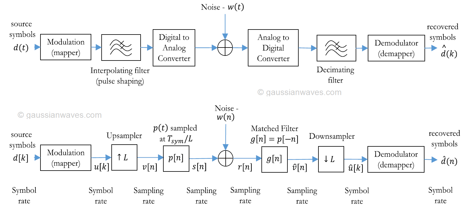
The interpolating filter at the transmitter is implemented in DSP as a chain of upsampler and a pulse shaping function. The upsampler inserts $latex L-1$ zeros between the successive incoming data samples and the pulse shaping filter fills in the zeros generated by the upsampler by using a pulse shaping function. On the other hand, the receiver contains a downsampler that keeps every $latex L^{th}$ sample starting from a specified offset. The factor $latex L$ denotes the oversampling factor or upsampling ratio which is given as the ratio of symbol period ($latex T_{sym}$) and the sampling period ($latex T_s$) or equivalently, the ratio of sampling rate $latex F_s$ and the symbol rate $latex F_{sym}$ as
$latex \displaystyle{L = \frac{T_{sym}}{T_s} = \frac{F_s}{F_{sym}}} \quad\quad (1) &s=1$
The implementation of impulse response of the most widely discussed pulsing shaping functions (filters) will follow in the next series of articles, followed by an example on a complete matched filter system with square-root raised-cosine pulse shaping.
Rate this article: [ratings]
Books by the author
[table id=23 /]
Topics in this chapter
[table id=27 /]