
5G NR PHY path:
BPSK →
QPSK →
π/2-BPSK →
NR resource block →
BER calculator
In one sentence: π/2-BPSK alternates between two BPSK constellations rotated by 90° so successive symbols do not stay on the same axis — lowering uplink PAPR for DFT-s-OFDM at low rates in 5G NR.
The 5G New Radio (NR) supports quadrature phase shift keying (QPSK), 16- quadrature amplitude modulation (16-QAM), 64 QAM and 256 QAM modulation schemes for both uplink and downlink [1][2]. This is same as in LTE.
Additionally, 5G NR supports π/2-BPSK in uplink (to be combined with OFDM with CP or DFT-s OFDM with CP)[1][2]. Utilization of π/2-BPSK in the uplink is aimed at providing further reduction of peak-to-average power ratio (PAPR) and boosting RF amplifier power efficiency at lower data-rates.
π/2 BPSK
π/2 BPSK uses two sets of BPSK constellations that are shifted by 90°. The constellation sets are selected depending on the position of the bits in the input sequence. Figure (1) depicts the two constellation sets for π/2 BPSK that are defined as per equation (1)
\[d[i] = \frac{e^{j \frac{\pi}{2} \left( i \; mod \; 2\right) }}{ \sqrt{2}} \left[ \left(1 – 2b[i] \right) + j \left(1 – 2b[i] \right)\right] \quad \quad (1) \]b[i] = input bits; i = position or index of input bits; d[i] = mapped bits (constellation points)

Equation (2) is for conventional BPSK – given for comparison. Figure (2) and Figure (3) depicts the ideal constellations and waveforms for BPSK and π/2 BPSK, when a long sequence of random input bits are input to the BPSK and π/2 BPSK modulators respectively. From the waveform, you may note that π/2 BPSK has more phase transitions than BPSK. Therefore π/2 BPSK also helps in better synchronization, especially for cases with long runs of 1s and 0s in the input sequence.
\[d[i] = \frac{1}{ \sqrt{2}} \left[ \left(1 – 2b[i] \right) + j \left(1 – 2b[i] \right)\right] \quad \quad (2)\]

Figure 4, illustrates the constellations for BPSK and π/2 BPSK when the sequence of mapped bits are corrupted by noise.

Note: Though the π/2 BPSK constellation looks like a QPSK constellation, they are not the same. Give it a thought !!!
Geometry, PAPR intuition, and a Python mapping
The constellation figures above already hint at the geometry. Standard BPSK places both symbols on the real axis ($latex +A$ or$latex -A$). π/2-BPSK (used in 5G NR uplink with DFT-s-OFDM) rotates the constellation by$latex \pi/2$ on alternate symbols so successive symbols are less likely to create large envelope peaks after pulse shaping.
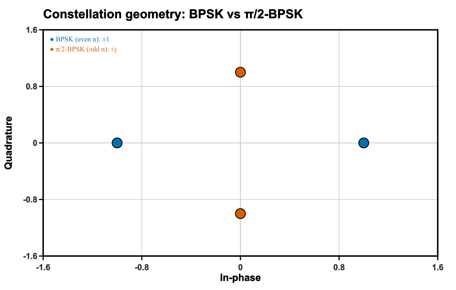
Mapping rule (complex baseband)
Let bits$latex b_n\in\{0,1\}$ map to$latex a_n = 1-2b_n\in\{+1,-1\}$. Then
\[ s_n = a_n \cdot e^{j n \pi / 2} = a_n \cdot j^{n} \]
So for even$latex n$,$latex s_n$ is real; for odd$latex n$,$latex s_n$ is imaginary. After DFT-s-OFDM / CP-OFDM, this reduces abrupt 180° I-axis reversals that drive PAPR.
Python: generate π/2-BPSK symbols
import numpy as np

def pi2_bpsk(bits):
    """bits: 0/1 array → complex π/2-BPSK symbols (unit energy)."""
    a = 1 - 2*np.asarray(bits, dtype=float)          # ±1
    n = np.arange(a.size)
    return a * (1j ** n)                             # rotate by n*π/2

bits = np.array([0,1,1,0,1,0,0,1])
s = pi2_bpsk(bits)
print(np.round(s, 3))
# Example: [ 1.+0.j  -0.-1.j  -1.+0.j  -0.+1.j ...]
What to check next: compare PAPR of pulse-shaped BPSK vs π/2-BPSK over the same bit stream; then place the symbols on DFT-s-OFDM as in 3GPP TS 38.211. Related tools: OFDM CP overhead, classic BPSK BER sim.
References
[1] 3GPP TS 38.201: Physical layer; General description (Release 16)
[2] 3GPP TS 38.211: Physical channels and modulation (Release 16)
[3] Gustav Gerald Vos, ‘Two-tone in-phase pi/2 binary phase-shift keying communication’, US patent number 10,931,492
FAQ
Why does 5G NR use π/2-BPSK instead of ordinary BPSK on the uplink? At low spectral efficiency, plain BPSK on DFT-s-OFDM can still produce a relatively peaky envelope. Alternating the BPSK constellation by $latex \pi/2$ each symbol keeps successive symbols from staying on the same axis, which reduces envelope variation (PAPR) and helps power-amplifier efficiency for coverage-limited UEs.
Is π/2-BPSK the same modulation as QPSK? No. Each π/2-BPSK symbol still carries one bit and uses a two-point alphabet; the allowed point set is simply rotated by 90° from one symbol to the next. QPSK uses four points and two bits per symbol. The rotation trick is about envelope continuity, not about packing more bits.
Where is π/2-BPSK specified and used? It appears in 3GPP TS 38.211 for NR uplink, typically together with DFT-s-OFDM (and in some cases CP-OFDM) for the lowest MCS values where coverage matters more than rate.
Dear Sir,
What will be the effect of complex noise (zero mean circullarly symmetric) on the BPSK (+1 for ‘0’ and -1 for’1′). Whether SNR will be same or different compare to the case when noise is real.
There is no bit transmitted on imaginary part. So it will not make any difference.
I want code matlab for faster than nyquist
hi my dear i want code MATLAB for faster than Nyquist signalization