The phenomenon of Rayleigh Flat fading and its simulation using Clarke’s model and Young’s model were discussed in the previous posts. The performance (Eb/N0 Vs BER) of BPSK modulation (with coherent detection) over Rayleigh Fading channel and its comparison over AWGN channel is discussed in this post.
[table “47” not found /]We first investigate the non-coherent detection of BPSK over Rayleigh Fading channel and then we move on to the coherent detection. For both the cases, we consider a simple flat fading Rayleigh channel (modeled as a – single tap filter – with complex impulse response – h). The channel also adds AWGN noise to the signal samples after it suffers from Rayleigh Fading.
The received signal y can be represented as
$$ y=hx+n $$
where n is the noise contributed by AWGN which is Gaussian distributed with zero mean and unit variance and h is the Rayleigh Fading response with zero mean and unit variance. (For a simple AWGN channel without Rayleigh Fading the received signal is represented as y=x+n).
Non-Coherent Detection:
In non-coherent detection, prior knowledge of the channel impulse response (“h” in this case) is not known at the receiver. Consider the BPSK signaling scheme with ‘x=+/- a’ being transmitted over such a channel as described above. This signaling scheme fails completely (in non coherent detection scheme), even in the absence of noise, since the phase of the received signal y is uniformly distributed between 0 and 2pi regardless of whether x[m]=+a or x[m]=-a is transmitted. So the non coherent detection of the BPSK signaling is not a suitable method of detection especially in a Fading environment.
Coherent Detection:
In coherent detection, the receiver has sufficient knowledge about the channel impulse response.Techniques like pilot transmissions are used to estimate the channel impulse response at the receiver, before the actual data transmission could begin. Lets consider that the channel impulse response estimate at receiver is known and is perfect & accurate.The transmitted symbols (‘x’) can be obtained from the received signal (‘y’) by the process of equalization as given below.
$$ \hat{y}=\frac{y}{h}=\frac{hx+n}{h}=x+z $$
here z is still an AWGN noise except for the scaling factor 1/h. Now the detection of x can be performed in a manner similar to the detection in AWGN channels.
The input binary bits to the BPSK modulation system are detected as
$$ \begin{matrix} r=real(\hat{y})=real(x+z) \\ \; \; \hat{d} =1, \; \; if \;r> 0 \\ \; \; \hat{d}=0 , \; \; if \; r< 0 \end{matrix} $$
Theoretical BER:
The theoretical BER for BPSK modulation scheme over Rayleigh fading channel (with AWGN noise) is given by
$$ P_{b} =\frac{1}{2} \left ( 1-\sqrt{\frac{E_{b}/N_{0}}{1+E_{b}/N_{0}}}\right) $$
The theoretical BER for BPSK modulation scheme over an AWGN channel is given here for comparison
$$ P_{b}=\frac{1}{2}erfc(\sqrt{E_{b}/N_{0}}) $$
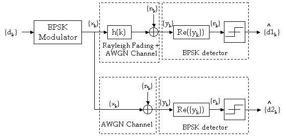
Simulation Model:
The following model is used for the simulation of BPSK over Rayleigh Fading channel and its comparison with AWGN channel
Matlab Code:
Check these books for matlab code
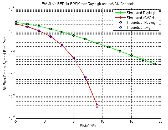
[table “47” not found /]Simulation Results:
The Simulated and theoretical performance curves (Eb/N0 Vs BER) for BPSK modulation over Rayleigh Fading channel and the AWGN is given below.
See also
[1]Eb/N0 Vs BER for BPSK over Rician Fading Channel
[2]Simulation of Rayleigh Fading ( Clarke’s Model – sum of sinusoids method)
[3]Performance comparison of Digital Modulation techniques
[4]BER Vs Eb/N0 for BPSK modulation over AWGN
[5]Rayleigh Fading Simulation – Young’s model
[6]Introduction to Fading Channels
Books by the author
[table “23” not found /]External Resources
[1]Theoretical expressions for BER under various conditions
[2]Capacity of MRC on correlated Rician Fading Channels
Hi,
Could you please explain to me why do you have these lines in your matlab code. What is it for?
simBER_rayleigh=zeros(1,length(EbN0dB));
simBER_awgn=zeros(1,length(EbN0dB));
I tried to cut these 2 lines and it still produces the same result.
Could you please let me know why you have to have these 2 lines in the matlab. Thank you so much.
simBER_rayleigh=zeros(1,length(EbN0dB));
simBER_awgn=zeros(1,length(EbN0dB));
These lines are used to initialize the arrays simBER_rayleigh and simBER_awgn to all zero values,
The code will work without these initializations in matlab. But it is a very bad programming practice not to initialize an array properly.
If you were to implement the same code in C/C++, the code implemented without definition and initialization of these arrays will not work.
It is always good to initialize all the arrays used in a program to proper values, otherwise, sometimes uninitialization may produce undesirable results.
Oh, great!
Thank you so much. that’s very clear.
You describe BPSK mod. single carrier over Rayleigh Channel and AWGN Channel. Yoy also simulate OFDM but in AWGN channel. Is any possible to simulate also OFDM in Rayleigh channel with similar parameter to BPSK single carrier and compare both. If I understand, BER for OFDM should be much better than single car. BPSK in Rayleigh channel????
Thanks in advance!!!!
n = noise*10^(-EbN0dB(i)/20); %Scaling the noise for required Eb/N0
Why divided by 20? Why not by 10?
Kind regards,
n = noise*10^(-EbN0dB(i)/20); %Scaling the noise for required Eb/N0
Why divided by 20? Why not by 10?
Kind regards,
hi there,
in frequency domain, can the signal model can be written as
Y = HX+N
where
Y=Fourier Transform(y),
H=Fourier Transform(h),
X=Fourier Transform(x), and
N=Fourier Transform(n)
Since it is a single tap channel, I think it will be as above not convulation form like Y = H*X + N. Am I corret? Thanks for response.
gka
Hi..
Can you help me by giving idea about rician channel effect on bpsk or QPSK . I am trying to find out BER v/s SNR characteristic on matlab
Hi Navneet,
For Rician Fading, three parameters are essential
1) Mean of the distribution
2) Variance
3) Rician Factor (k)
Rician Fading contains a direct Line Of Sight (LOS) signal along with other reflected signal. In fact Rayleigh Fading is a special form of Rician fading wherein the LOS signal is absent.
Suppose, if in Rayleigh Fading the received signal is given by
y = h*x + n
where, ‘h’ is bi-variate randomly distributed (see the matlab code above).
and ‘n’ is the AWGN noise.
The ‘h’ component acts as random fluctuations in phase for both sine and cos terms of the transmitted signal ‘x’.
In Rician Fading, this can be extended to include a LOS component of ‘x’
The equation for Rician Fading then becomes
y = h*x + k*x + n
Here K is the Rician Factor usually expressed in dB. Convert the given Rician Factor (K) to linear scale and multiply it with the transmitted signal x.
The above equation has three components
1) h*x -> Adding random fluctuations in phase of ‘x’ (Similar to Rayleigh Fading)
2) k*x -> Attenuated direct Line Of Sight signal ‘x’, where K is the Rician Factor in linear scale
3) n -> AWGN noise
Check out this link that will give you a headstart
Simulation Of Flat Fading Using MATLAB
Hope this helps
Thanks a lot.. 🙂
One thing more i would like to know is, when we compute theoretical BER in case of both AWGN and Rayleigh channels the formula differs.. So now in case of Ricean Channel the formula used for theoretical calculation will be same as that of Rayleigh or some what different???
It will be very kind of you if you will reply…
The Theoritical BER for BPSK over Rician Fading channel (with AWGN ) is given by
$latex P_b = Q \left[ \sqrt{ \frac{2K \left( E_b/N_0 \right) }{K+(E_b/N_0)}} \right] &s=2$
where K is the Rician Factor and Q(.) is the complementary error function given by
$latex Q(x) = \frac{1}{\sqrt{2 \pi}}\int_{x}^{\infty} exp(\frac{-y^2}{2})dy &s=2$
Hi!
I tried to implement Rician fading on matlab.. Bt the confusion is that ber is increasing with SNR in the graph.. which according to me should not be the case…
May you please tell why is that happening??
Please send me the code using the private messaging feature in the website. Go to my profile and click private message and copy+paste the code and send it across..
I will have a look…
Thank You Very much..
Will again ask for help if needed.. 🙂
Have a nice day
Hi Navneet
Hi,
I have written a detailed article on simulating BPSK over Rician Channel. Please take a look here
Click here for the article
You can use the code available here. Please modify the code that I sent earlier (as given in the article)
Thanks for your curiosity and support
Hi!
Will you please tell me the code on ‘How can we implement different diversity schemes like frequency, time, spatial diversity on Awgn and Rayleigh channel in case of BPSK and QPSK??’
Thanks..
Hi..
I do not have the code for diversity schemes .. I will post it once I have it .. In the meantime, if you have the code, you too can contribute it in this website.
BTW, time diversity is easier to implement. All you need to do is to have an interleaver at the transmitter and a de-interleaver at the receiver. Check this article for an hint on interleaver design.
Interleaver design for RS codes
For frequency diversity, you can use OFDM or spread spectrum.
OFDM
Spread Spectrum
Spatial diversity is essentially MIMO techniques (can also be transmit diversity or receive diversity).
This document may provide you some hint to start.
MIMO Diversity Techniques
Thanks a lot.. 🙂
I m working on the same and will surely post if i’ll be successful..
Thanks
Hi Mathuranathan,
Thank you for your information, it is very helpful. Now I am writing a paper based on equation $latex P_{b} =\frac{1}{2} \left ( 1-\sqrt{\frac{E_{b}/N_{0}}{1+E_{b}/N_{0}}}\right) $. Do you know where to find the original source this equation come from? Because I need to cite it very formally. Thank you very much.
Hi Sherry,
Please refer the following links for proper reference.
[1] Cho, K., and Yoon, D., “On the general BER expression of one- and two-dimensional amplitude modulations”, IEEE Trans. Commun., Vol. 50, Number 7, pp. 1074-1080, 2002.
[2] Lee, P. J., “Computation of the bit error rate of coherent M-ary PSK with Gray code bit mapping”, IEEE Trans. Commun., Vol. COM-34, Number 5, pp. 488-491, 1986.
[3] Lindsey, W. C., “Error probabilities for Rician fading multichannel reception of binary and N-ary signals”, IEEE Trans. Inform. Theory, Vol. IT-10, pp. 339-350, 1964.
[4] Simon, M. K , Hinedi, S. M., and Lindsey, W. C., Digital Communication Techniques – Signal Design and Detection, Prentice-Hall, 1995.
[5] Simon, M. K., and Alouini, M. S., Digital Communication over Fading Channels – A Unified Approach to Performance Analysis, 1st ed., Wiley, 2000.
Also
http://www.mathworks.in/help/toolbox/comm/ug/bsvzixi.html#bq5fugh
Thank you so much, Mathuranathan. But here comes new problems for my work. Do you know what are the equations of M-ary PSK and M-QAM in Rayleigh fading channel (with with AWGN noise)? Or you may know how to derive them?
Hi Sherry,
All the theoretically derived performance functions are available here
berfading function Matlab
Hi Mathuranathan, I am grateful for your help. I will read those documents carefully. Thank you again.
Sorry, the equation above is the theoretical BER for BPSK modulation scheme over Rayleigh fading channel (with AWGN noise). Thank you again.
What is about frequency selective fading ? Does anyone share an idea ? I got trouble. Thanks
In the above example, the Rayleigh Fading is modelled as a single tap filter, meaning that there is only one path from tranmitter to the receiver. In frequency selective fading cases, there need to be more than one path.
Following example illustrates how to simulate frequency selective fading using two paths.
Two-ray Rayleigh Fading Model – Frequency Selective fading
The complex channel impulse response for a two ray model is given by
$latex h(t) = \alpha_1 exp(j \phi_1) \delta (t) + \alpha_2 exp(j \phi_2) \delta (t- \tau) $
Here the amplitudes $latex \alpha_1 $ and $latex \alpha_2 $ are independent and Rayleigh distributed, the phases $latex \phi_1 $ and $latex \phi_2 $ are independent and uniformly distributed and $latex \tau $ is the time delay between two multipath components.
The above code models only a single tap (no-multipath) flat fading scenario (The second term in the complex channel response is zero).
The above code can be modified to accomodate two tap Rayleigh Frequency Fading Channel. But the receiver has to be modelled to accept and process multipaths.
can you please guide me how to generate matlab code to Plot waterfall curve for BER vs Eb/No for Qpsk adding rayleigh fading effects to signal?
Code available in the ebook for BPSK https://www.gaussianwaves.com/s…
It also contains code to simulate QPSK over AWGN. Both the chapters can be combined to address your question
hi
how to add Rayleigh channel
for calculating BER
Code available in the ebook https://www.gaussianwaves.com/s…
Could not publish here due to copyright concerns. Sorry for that
can i get ofdm matlab code?
Code available in the ebook https://www.gaussianwaves.com/simulation-of-digital-communication-systems-using-matlab-ebook/
Could not publish here due to copyright concerns. Sorry for that
hi sir
can you send me matlab code for wimax physical layer over multipath fading through my email
I do not have the code. Thanks for your interest
Hi everyone,
I bought your book but now I would like to add path loss exponent in fading. How can I add.
y_rayleigh=h*x+n
Where can I add the distance and path loss exponent.
Please help me.
Thanks in advance.
hello friends
i want to plot the ber in rayleigh channel,but my graph is false.who can say why?
thanks
my code is as the following:
N=10^6; %Number of BPSK symbols to transmit
M = 4; %constellation
m = log2(M); %number of bits in eath symbol
SNR = 0:2:20; %signal to noise ratio(dB)
var_n = 0.01;
numSNR = length(SNR);
simBER_rayleigh =zeros(1 ,length(SNR));
x=randi([0,1] ,1 ,N);
%%%%%%%%%%%%%%%%%%%main progress%%%%%%%%%%%%%%%%%%%%%%
for i = 1:numSNR
noise = 1/sqrt(2) *(randn(1 ,N) +1i*randn(1 ,N));
% n = sqrt (var_n / var (n) )*n;
h = 1/sqrt(2) *(randn(1 ,N) +1i*randn(1 ,N));
n = noise.*10^(-SNR(i) /20);
y_rayleigh =h.*x +n;
%Coherent Receiver for Rayleigh Channel
y_rayleigh_cap = y_rayleigh./h;
r_rayleigh = real(y_rayleigh_cap)>0;
simBER_rayleigh(i) = sum(xor (x ,r_rayleigh));
end
%%%%%%%%%%%%%%%%%%%%%%%%%output%%%%%%%%%%%%%%%%
BER = simBER_rayleigh(1 ,:) /N;
Hello my friends
i want to plot the ‘BER Performance in Multipath Rayleigh Channel with 4-psk Modulation’ with matlab functinon,because it’s fast run.i use the filter for equalization after adding the awgn.filter coefficients is the channel gain.channel gain for different SNR is constant.but filter response in Nan!who’s know why?
thanks
%%%%%%%%%%%%%%%%%%%%%%%%%in the name of ALLAH%%%%%%%%%%%%%%%%
clc
clear all
close all
%%%%%%%%%%%%%%%%%%%%%%%%%initial values%%%%%%%%%%%%%%%%%%%%%%%%%%%%
length_x_in = 1e6; %lenght of x_in
M = 4; %constellation
m = log2(M); %number of bits in eath symbol
SNR_range = 0:5:30; %signal to noise ratio(dB)
t_sampling = 1;
f_doppler = .1;
numSNR = length(SNR_range);
tau = [1 2 3 4];
pdb = [1 .6 .8 .5];
%Channel Defintion
hchan_rayleigh = rayleighchan(t_sampling ,f_doppler ,tau ,pdb); %Rayleigh Channel
hchan_rayleigh.ResetBeforeFiltering = 0;
BER = zeros(1 ,numSNR); %BER Vector
i = 0;
for SNR = SNR_range
i = i + 1;
%%%%%%%%%%%%%%%%%%%%%inputs%%%%%%%%%%%%%%%%%%%%%%%%
x_in = randi ([0,M-1] ,length_x_in ,1); %message signal
x_in_mod = pskmod(x_in ,M); %x_in Modulation
%%%%%%%%%%%%%%%%%%%%%%%%%%%%%main progress%%%%%%%%%%%%%%%%%%%%%%%%%%%%%%%
y = filter(hchan_rayleigh ,x_in_mod); %Received Signal Through Rayleigh Channel
y_noisy = awgn(y ,SNR);
y_compensate = filter(1 ,hchan_rayleigh.PathGains ,y_noisy); %Compensate
y_demod = pskdemod(y_compensate ,M); %y_compensate Demdulation
BER(i) = sum (xor(x_in ,y_demod)); %BER Counter
end
%%%%%%%%%%%%%%%%%%%%%%%%%%outputs%%%%%%%%%%%%
BER_Empirical = BER/length_x_in; %BER_Empirical
BER_theory = berfading(SNR_range ,’psk’ ,M ,1); %BER_theory
%%%%%%%%%%%%%%%%%%%%%%%%%%%%plots%%%%%%%%%%%%%
semilogy(SNR_range ,BER_Empirical ,’r-‘ ,SNR_range ,BER_theory ,’b-*’)
legend(‘Empirical BER’ ,’Theory BER’)
xlabel(‘SNR’) ; ylabel(‘BER’)
title(‘BER Performance in Rayleigh Channel with 4-psk Modulation’)
Hi dear all,I need matlab code for CRLB for DOA estimation .
Hello Sir,
The complex Channel Impulse Response is given by the following expression: ‘ ImP=(cos(D(:,4)*pi/180)+sqrt(-1)*sin(D(:,4)*pi/180)).*10.^(D(:,3)./20); ‘
Please, can you clarify to me what is D.
Thank you so much,
I suspect that D is a matrix containing mix of parameters, where the third column of the matrix contains a vector of timebase and fourth column of D contains some scaling factor for power (say k) expressed in dB.
you can re-write the equation as follows for more clarity
t=D(:,4); %extract timebase or phase values
kdB = D(:,3); %extract kdB values
k = 10.^(kdB./20);%linear scale , converted to amplitude level
Now the equation becomes
(cos(t*pi/180)+sqrt(-1)*sin(t*pi/180)).*k ‘
Looks like , the equation is for a complex sinusoid of form
k*(cos(A)+j sin(B))
Hello Sir,
Please, can you help me to convert (using Matlab) each image into a binary data then to plot bit error rate for each one (in order to compare the bit error rate for the two figures).
I need your help please.
Attached are the figures.
Thank you so much in advance for your help and support.
please Sir can you help me small code matlab to generate the impulse response of rice channel?
hello
can i have code of BER for PAM,OQPSK and DPSK over awgn , rician and relight channels in matlab
https://uploads.disquscdn.com/images/a4a57bd3710f7e5705dd7feda0e9d65972f05ebfa65e5925edad587c235133bb.jpg can u provide the matlab code for Average capacity at the ith subcarrier versus peak transmit power,
Ps, in case of collision-free (no-interference) and interference from only PU,
only SU-2 and both PU and SU-2 with P = 5 dB and I = 2 dB.
−2,in case of cognitive radios The output is shown below in the figure
I don’t have the code. Anyways thanks for asking.