Fading & Diversity — 6 lessons (same on every page in this path)
1. Rayleigh BER → 2. Clarke’s model → 3. Young’s model (you are here) → 4. SIMO models → 5. Selection combining → 6. MRC
Tools: BER vs Eb/N0 · 3GPP TDL · CDL / Doppler
Lesson 3 of 6. Another standard way to generate Rayleigh processes after Clarke. Next we add antennas: SIMO / receive-diversity channel models.
Introduction
Young and Beaulieu’s construction is a way to generate a time series of correlated Rayleigh fades with the classical Jakes (Clarke) Doppler spectrum. It is a modification of Smith’s inverse-DFT method. It is not, by itself, a frequency-selective channel. Frequency selectivity needs a tapped delay line, with one such process on each tap. What this article builds is the complex coefficient of a flat fading channel, evolving in time.
The physical picture is the usual one. Many paths arrive with different delays and angles, none of them a dominant line of sight, so the baseband coefficient is a zero-mean complex Gaussian and its amplitude is Rayleigh. Motion between the transmitter and the receiver spreads that coefficient in frequency. The spectrum used here is the U-shaped Jakes spectrum, band-limited to the maximum Doppler frequency \(f_d\).
Young’s model
In the previous article, the characteristics and types of fading was discussed. Rayleigh Fading channel with Doppler shift is considered in this article.
Consider a channel affected by both Rayleigh Fading phenomena and Doppler Shift. Rayleigh Fading is caused due to multipath reflections of the received signal before it reaches the receiver and the Doppler Shift is caused due to the difference in the relative velocity/motion between the transmitter and the receiver. This scenario is encountered in day to day mobile communications.
Several algorithms produce correlated Rayleigh samples. David J. Young and Norman C. Beaulieu, in “The Generation of Correlated Rayleigh Random Variates by Inverse Discrete Fourier Transform” [1], start from Smith’s IDFT method and rearrange it. Their rearrangement uses one IDFT instead of two, and about two thirds of the memory, because a single complex transform supplies both quadrature components.
Rayleigh Fading can be simulated by adding two Gaussian Random variables as mentioned in my previous post. The effect of Doppler shift is incorporated by modeling the Doppler effect as a frequency domain filter.
The model proposed by Young et.al is shown below.

The Fading effect + Doppler Shift is simulated by multiplying the Gaussian Random variables and the Doppler Shift’s Frequency domain representation. Then IDFT is performed to bring them into time domain representation. The Doppler Filter used to represent the Doppler Shift effect is derived in Young’s paper.
Let \(f_m = f_d/f_s\) be the maximum Doppler frequency normalised by the sampling rate, and let \(k_m = \lfloor N f_m \rfloor\). The Doppler filter that shapes an \(N\)-point white spectrum is
\[F[k]=\begin{cases} 0, & k=0 \\[4pt] \sqrt{\dfrac{1}{2\sqrt{1-\left(\dfrac{k}{N f_m}\right)^2}}}, & k=1,2,\ldots,k_m-1 \\[6pt] \sqrt{\dfrac{k_m}{2}\left[\dfrac{\pi}{2}-\arctan\left(\dfrac{k_m-1}{\sqrt{2k_m-1}}\right)\right]}, & k=k_m \\[6pt] 0, & k=k_m+1,\ldots,N-k_m-1 \\[4pt] \sqrt{\dfrac{k_m}{2}\left[\dfrac{\pi}{2}-\arctan\left(\dfrac{k_m-1}{\sqrt{2k_m-1}}\right)\right]}, & k=N-k_m \\[6pt] \sqrt{\dfrac{1}{2\sqrt{1-\left(\dfrac{N-k}{N f_m}\right)^2}}}, & k=N-k_m+1,\ldots,N-1 \end{cases}\]The bin at \(k = 0\) is set to zero in the paper, and the area under the singularity of the Jakes spectrum is placed in the bins \(k_m\) and \(N-k_m\). An older rendering of this equation on the page wrote a spurious backslash in front of the zero at \(k = 0\). The cases above are the filter as stated by Young and Beaulieu. \(N\) has to be large enough that \(k_m \ge 1\), otherwise the Doppler span occupies none of the DFT bins.
Python realisation
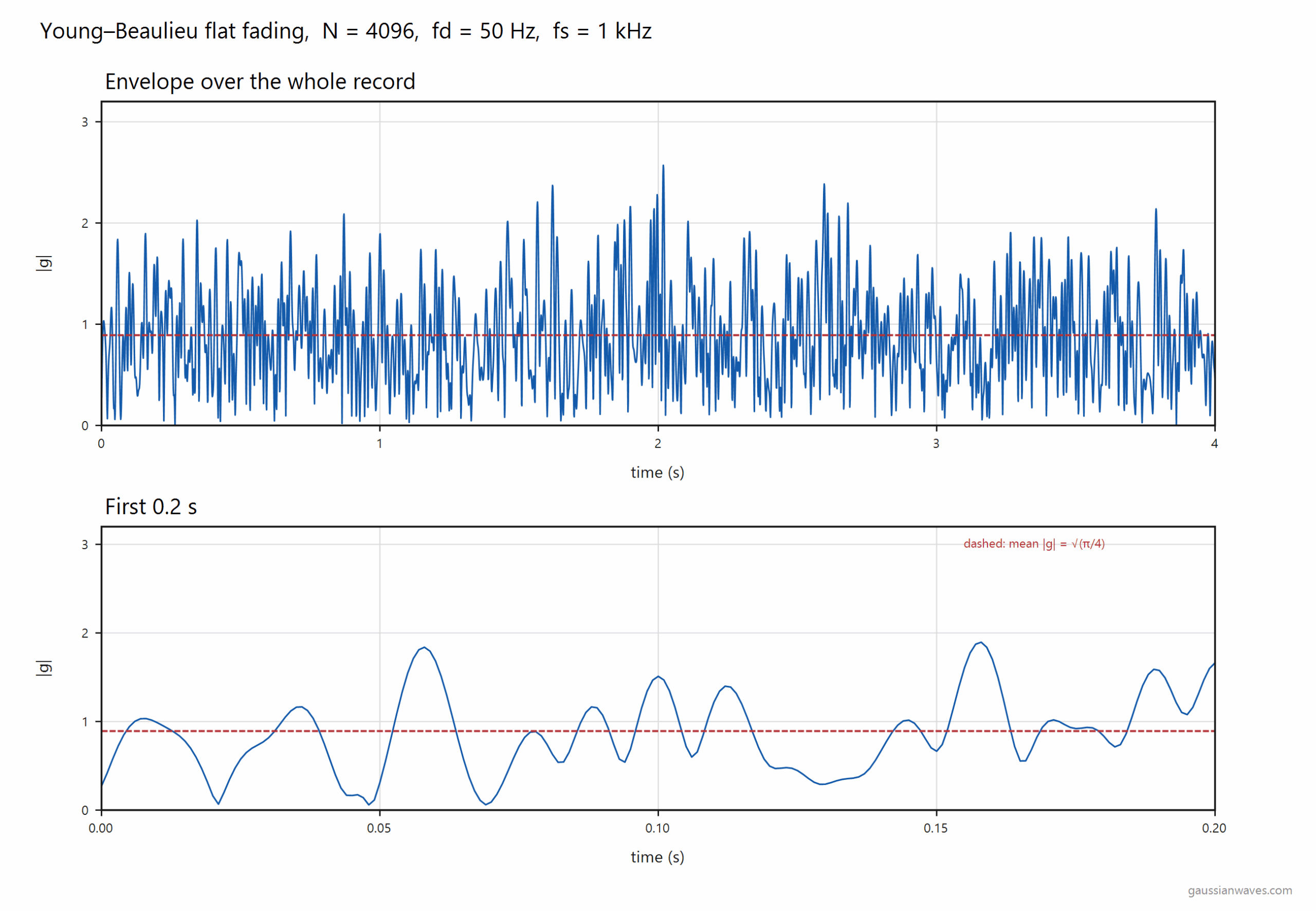
One complex IDFT produces the complex envelope. The output is scaled so that \(E[|g|^2] = 1\), which makes \(|g|\) a unit-power Rayleigh amplitude (scale \(1/\sqrt{2}\)). The example uses \(N = 4096\), \(f_d = 50\) Hz and \(f_s = 1\) kHz. The time-series plot further down is one draw at these parameters. A useful check, not done by the snippet, is to compare the measured autocorrelation against \(J_0(2\pi f_d \tau)\).
import numpy as np

def young_rayleigh(N, fd, fs, rng=None):
    """Complex flat-fading envelope with the Jakes spectrum, unit average power.

    fd and fs are in hertz. N is the DFT length. Young and Beaulieu, IEEE
    Trans. Commun., vol. 48, pp. 1114-1127, July 2000.
    """
    rng = np.random.default_rng() if rng is None else rng
    fm = fd / fs
    km = int(np.floor(fm * N))
    if km < 1:
        raise ValueError("Doppler span is empty. Increase N or fd/fs.")

    F = np.zeros(N)
    k = np.arange(1, km)
    F[k] = np.sqrt(1.0 / (2.0 * np.sqrt(1.0 - (k / (N * fm)) ** 2)))
    edge = np.sqrt((km / 2.0) * (np.pi / 2.0 - np.arctan((km - 1) / np.sqrt(2 * km - 1))))
    F[km] = edge
    F[N - km] = edge
    k2 = np.arange(N - km + 1, N)
    F[k2] = np.sqrt(1.0 / (2.0 * np.sqrt(1.0 - ((N - k2) / (N * fm)) ** 2)))

    white = (rng.normal(size=N) + 1j * rng.normal(size=N)) / np.sqrt(2.0)
    # numpy's ifft carries 1/N; multiply it back so the filter gain is F[k]
    g = np.fft.ifft(F * white) * N
    g /= np.sqrt(np.mean(np.abs(g) ** 2))
    return g

N, fd, fs = 4096, 50.0, 1000.0
g = young_rayleigh(N, fd, fs, rng=np.random.default_rng(2))
t = np.arange(N) / fs
print("samples", N, " duration %.2f s" % t[-1])
print("E[|g|^2] = %.4f,   mean amplitude = %.4f (Rayleigh theory %.4f)" % (
    np.mean(np.abs(g) ** 2), np.mean(np.abs(g)), np.sqrt(np.pi / 4.0)))
Matlab Code
Check this book for full Matlab code.
Simulation of Digital Communication Systems Using Matlab – by Mathuranathan Viswanathan
Matlab code Output:
Reference:
See also
[1]Eb/N0 Vs BER for BPSK over Rayleigh Channel and AWGN Channel
[2]Simulation of Rayleigh Fading ( Clarke’s Model – sum of sinusoids method)
[3]Performance comparison of Digital Modulation techniques
[4]BER Vs Eb/N0 for BPSK modulation over AWGN
[5]Introduction to Fading Channels
External Resources
[1]Theoretical expressions for BER under various conditions
[2] The Manchester link that used to sit here no longer resolves. For the Doppler spectrum itself, Clarke’s 1968 paper and the Young–Beaulieu paper cited above are the stable references.
Python sketch: Rayleigh envelope from complex Gaussians
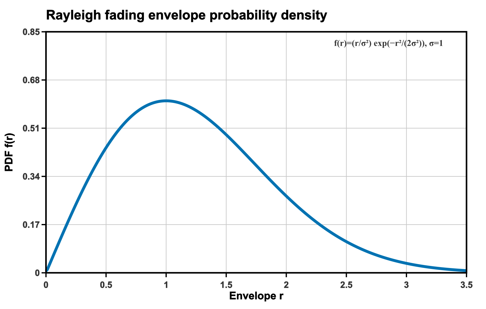
Clarke’s sum-of-sinusoids builds time-correlated \(h(t)\). The marginal distribution of a well-normalized isotropic complex Gaussian still has Rayleigh envelope:
import numpy as np

N = 200_000
h = (np.random.randn(N) + 1j*np.random.randn(N)) / np.sqrt(2)  # E[|h|^2]=1
r = np.abs(h)
# crude PDF check: mean of Rayleigh(σ=1/√2) is sqrt(π/4) ≈ 0.886
print('mean envelope ~', r.mean(), ' (theory 0.886)')
print('E[|h|^2] ~', np.mean(np.abs(h)**2))
For standardized 5G delay profiles after you leave flat fading, jump to the 3GPP TDL calculator and the TDL multipath article.
FAQ
What is the recommended reading order? Follow the six lessons at the top: Rayleigh BER → Clarke → Young → SIMO models → Selection combining → MRC. Optional branch: Rician fading.
well actually I’m planning to do it in vhdl for test bench. but I got the idea. Thank you sir
well actually I’m planning to do it in vhdl for test bench. but I got the idea. Thank you sir
Hi,
Could you please explain how we can use FFT and IFFT in order to solve specific problem in discrete domain? I’m glad if you can publish another post for that.
Thanks.
Can you elaborate ?
Basically I just need to know how FFT and IFFT works to compute Fourier transform and Inv. Fourier transform in discrete domain.
As a example ,lets say we want to model OFDM Transmission using FFT/IFFT (lets say in MatLab). Can you explain the approach I should follow in order to use FFT and IFFT at receiver and transmitter with out using direct formulas?
Thank You.
Hi Upul,
Please follow this excellent tutorial FFT/IFFT in OFDM
In the meantime, I might try to make an article.
Thank you very much for your support…
Hey Mathuranathan, I am implementing differential space time modulation and it’s purpose is to do detection without CSI. I have managed to implement it with a time invariant channel but now I want to see how it performs in a slow time varying channel at various doppler spreads….and the theory says I should use the Jakes model to have a relationship between one channel matrix to the next…by multiplying one channel matrix by some value obtained through zeroth order bessel function of first kind….But it just doesn’t give sensible results 🙁 Kindly assist on this implementation of a time varying channel that depends on doppler spread using Jakes model.
Hi Jasper,
Please check my reply for one of the similar topics in our forums for implementing a time varying channel.
https://www.gaussianwaves.com/forums/topic/time-varying-channel/