“What is the best filter that I should use? FIR or IIR ?” is often the question asked by many. There exists two different types of Linear Time Invariant (LTI) filters from transfer function standpoint : FIR (Finite Impulse Response) and IIR (Infinite Impulse Response) filters and myriad design techniques for designing them. The mere fact that there exists so many techniques for designing a filter, suggests that there is no single optimal filter design. One has to weigh-in the pros and cons of choosing a filter design by considering the factors discussed here.
Before proceeding to know the secrets of choosing a filter, I urge you to brush up the fundamentals of digital filter design.
Design specification:
A filter design starts with a specification. We may have a simple specification that just calls for removing an unwanted frequency component or it can be a complete design specification that calls for various parameters like – amount of ripples allowed in passband, stop band attenuation, transition width etc.., The design specification usually calls for satisfying one or more of the following:
● Desired Magnitude response – \(| H_{spec}(\omega)|\)
● Desired Phase response – \(\angle H_{spec}(\omega)\)
● Tolerance specifications – that specifies how much the filter response is allowed to vary when compared with ideal response. Examples include how much ripples allowed in passband, stop band etc..,
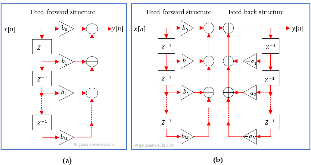
Given the specification above, the goal of a filter design process to choose the parameters \(M\), \(N\), \(b_k\) and \(a_k\), such that the transfer function of the filter

yields the desired response: \(H(\omega) \approx H_{spec} (\omega) \). In other words, the design process also involves choosing the number and location of the zeros zeros (\(z_i\)) and poles (\(p_j\)) in the pole-zero plot.
Two types of filter can manifest from the given transfer function above.
● When \(N=0\), there is no feedback in the filter structure, no poles in the pole-zero plot (in fact all the poles sit at the origin). The impulse response of such filter dies out (becomes zero) beyond certain point of time and it is classified as Finite Impulse Response (FIR) filter. It provides linear phase characteristic in the passband.
● When \(N>1\), the filter structure is characterized by the presence of feedback elements. Due to the presence of feedback elements, the impulse response of the filter may not become zero beyond certain point, but continues indefinitely and hence the name Infinite Impulse Response (IIR) filter.
● Caution: In most cases, the presence of feedback elements provide infinite impulse response. It is not always true. There are some exceptional cases where the presence of feedback structure may result in finite impulse response. For example, a moving average filter will have a finite impulse response. The output of a moving average filter can be described using a recursive formula, which will result in a structure with feedback elements.
General considerations in design:
As specified earlier, the choice of filter and the design process depends on design specification, application and the performance issues associates with them. However, the following general considerations are applied in practical design.
Minimizing number of computations
In order to minimize memory requirements for storing the filter co-efficients \(\left\{a_k\right\}\), \(\left\{ b_k \right\}\) and to minimize the number of computations, ideally we would like \(N+M\) to be as small as possible. For the same specification, IIR filters result in much lower order when compared to its FIR counter part. Therefore, IIR filters are efficient when viewed from this standpoint.
Need for real-time processing
The given application may require processing of input samples in real-time or the input samples may exist in a recorded state (example: video/audio playback, image processing applications, audio compression). From this perspective, we have two types of filter systems
● Causal Filter
— Filter output depends on present and past input samples, not on the future samples. The output may also depend on the past output samples, as in IIR filters. Strictly no future samples.
— Such filters are very much suited for real-time applications.
● Non-Causal Filter
— There are many practical cases where a non-causal filter is required. Typically, such application warrants some form of post-processing, where the entire data stream is already stored in memory.
— In such cases, a filter can be designed that can take in all type of input samples : present, past and future, for processing. These filters are classified as non-causal filters.
— Non-causal filters have much simpler design methods.
It can be often seen in many signal processing texts, that the causal filters are practically realizable. That does not mean non-causal filters are not practically implementable. In fact both types of filters are implementable and you can see them in many systems today. The question you must ask is : whether your application requires real-time processing or processing of pre-recorded samples. If the application requires real-time processing, causal filters must be used. Otherwise, non-causal filters can be used.
Consequences of causal filter:
If the application requires real-time processing, causal filters are the only choice for implementation. Following consequences must be considered if causality is desired.
Ideal filters with finite bands of zero response (example: brick-wall filters), cannot be implemented using causal filter structure. A direct consequence of causal filter is that the response cannot be ideal. Hence, we must design the filter that provides a close approximation to the desired response . If tolerance specification is given, it has to be met.
For example, in the case of designing a low pass filter with given passband frequency (\(\omega_P\)) and stopband frequencies (\(\omega_S\)), additional tolerance specifications like allowable passband ripple factor (\(\delta_P\)), stopband ripple factor (\(\delta_S\)) need to be considered for the design,. Therefore, the practical filter design involves choosing \(\omega_P, \omega_S, \delta_P\) and \(\delta_S\) and then designing the filter with \(N, M, \left \{a_k\right \}\) and \(\left \{b_k\right \}\) that satisfies all the given requirements/responses. Often, iterative procedures may be required to satisfy all the above (example: Parks and McClellan algorithm used for designing optimal causal FIR filters [1]).

For a causal filter, frequency response’s real part \(H_R(\omega)\) and the imaginary part \(H_I(\omega)\) become Hilbert transform pair [2]. Hence the magnitude and phase responses become interdependent.
Stability
For a causal LTI digital filter will be BIBO (Bounded Input Bounded Output) stable, if and only if the impulse response \(h[n]\) is absolutely summable.

Impulse response of FIR filters are always bounded and hence they are inherently stable. On the other hand, an IIR filter may become unstable if not designed properly.
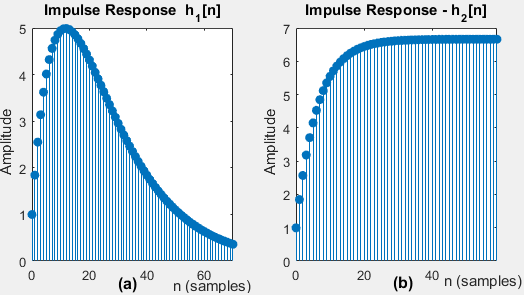
Consider an IIR filter implemented using a floating point processor that has enough accuracy to represent all the coefficients in the transfer function below

The corresponding impulse response \(h_1[n]\) is plotted in Figure 3(a). The plot shows that the impulse response decays rapidly to zero as \(n\) increases. For this case, the sum in equation (2) will be finite. Hence this IIR filter is stable.
Suppose, if we were to implement the same filter in a fixed point processor and we are forced to round-off the co-efficients to 2 digits after the decimal point, the same transfer function looks like this

The corresponding impulse response \(h_2[n]\) plotted in Figure 3(b) shows that the impulse response increases rapidly towards a constant value as \(n\) increases. For this case, the sum in equation (2) will tend to infinity. Hence the implemented IIR filter is unstable.
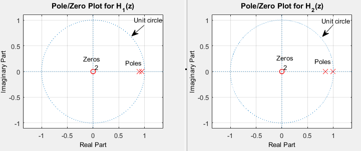
Therefore, it is imperative that an IIR filter implementation need to be tested for stability. To analyze the stability of the filter, the infinite sum in equation (2) need to be computed and it is often difficult to compute this sum. Analysis of pole-zero plot is an alternate solution for this problem. To have a stable causal filter, the poles of the transfer function should lie completely strictly inside the unit circle on the pole-zero plot. The pole-zero plot for the above given transfer functions \(H_1(z)\),\(H_2(z)\) are plotted in Figure 4. It shows that for the transfer function \(H_1(z)\), all the poles lie within the unit circle (the region of stability) and hence it is a stable IIR filter. On the other hand, for the transfer function \(H_2(z)\), one poles lie exactly on the unit circle (ie, it is just out of the region of stability) and hence it is an unstable IIR filter.
Linear phase requirement
In many signal processing applications, it is needed that a digital filter should not alter the angular relationship between the real and imaginary components of a signal, especially in the passband. In otherwords, the phase relationship between the signal components should be preserved in the filter’s passband. If not, we have phase distortion.
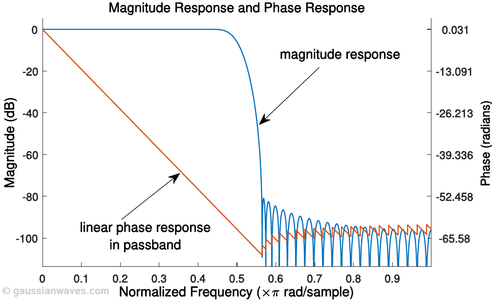
Phase distortion is a concern in many signal processing applications. For example, in phase modulations like GMSK [3],the entire demodulation process hinges on the phase relationship between the inphase and quadrature components of the incoming signal. If we have a phase distorting filter in the demodulation chain, the entire detection process goes for a toss. Hence, we have to pay attention to the phase characteristics of such filters. To have no phase distortion when processing a signal through a filter, every spectral component of the signal inside the passband should be delayed by the same amount time delay measured in samples. In other words, the phase response \(\phi(\omega)\) in the passband should be a linear function (straight line) of frequency (except for the phase wraps at the band edges). A filter that satisfies this property is called a linear phase filter. FIR filters provide perfect linear phase characteristic in the passband region (Figure 5) and hence avoids phase distortion. All IIR filters provide non-linear phase characteristic. If a real-time application warrants for zero phase distortion, FIR filters are the immediate choice for design.
It is intuitive to see the phase response of a generalized linear phase filter should follow the relationship \(\phi(\omega) = -m \omega + c\), where \(m\) is the slope and \(c\) is the intercept when viewing the linear relationship between the frequency and the phase response in the passband (Figure 5). The phase delay and group delay are the important filter characteristics considered for ascertaining the phase distortion and they relate to the intercept \(c\) and the slope \(m\) of the phase response in the passband. Linear phase filters are characterized by constant group delay. Any deviation in the group delay from the constant value inside the passband, indicates presence of certain degree of non-linearity in the phase and hence causes phase distortion.
Phase delay is the time delay experienced by each spectral component of the input signal. For a filter with the frequency response \(H(\omega)\), the phase delay response \(\tau_p\) defined in terms of phase response \(\phi(\omega) = \angle H(\omega)\) as

Group delay is the delay experienced by a group of spectral components within a narrow frequency interval about \(\omega\) [4]. The group delay response \(\tau_g(\omega)\) is defined as the negative derivative of the phase response \(\omega\).

For the generalized linear phase filter, the group delay and phase delay are given by

Summary of design choices
● IIR filters are efficient, they can provide similar magnitude response for fewer coefficients or lower sidelobes for same number of coefficients
● For linear phase requirement, FIR filters are the immediate choice for the design
● FIR filters are inherently stable. IIR filters are susceptible to finite length words effects of fixed point arithmetic and hence the design has to be rigorously tested for stability.
● IIR filters provide less average delay compared to its equivalent FIR counterpart. If the filter has to be used in a feedback path in a system, the amount of filter delay is very critical as it affects the stability of the overall system.
● Given a specification, an IIR design can be easily deduced based on closed-form expressions. However, satisfying the design requirements using an FIR design generally requires iterative procedures.
References:
Topics in this chapter
[table “31” not found /]Books by the author
[table “23” not found /]
Hello Author,
Thanks for this wonderful blog! I have a doubt.From the section “Minimizing number of computations”, I understand N+M has to be less and FIR would be efficient, But In the text IIR is mentioned to be efficient. Am I missing any thing here?
Generally FIR filters are computationally more intensive compared to their IIR counterparts. This is because, for the same design specification, FIR filters would need more filter coefficients compared to the number of coefficients in the IIR design.
However, we can apply multirate processing method to improve the overall computation efficiency of the design. In multirate processing, we use decimation and interpolation operations that helps us omit some calculations if FIR filters are used in such designs. IIR filters are not suited for such applications (every output has to be individually calculated and we cannot omit intermediate calculations). Therefore, multirate processing with FIR, since many calculations can be omitted, is far more efficient compared to standalone IIR design.
Thanks for the great explanation. I see that Figure 5 is missing. Is there anyway you can re-upload it if it has gone missing?
Thank you for the feedback. The figure is re-uploaded.