The medium between the transmitting antenna and the receiving antenna is generally termed as “channel”. In wireless transmission, the characteristics of the signal changes as it travels from the transmitter to the receiver. The signal characteristics are due to several phenomena: 1) existence of line of sight path between the antennas, 2) reflection, refraction and diffraction of the signal due to the objects in between the antennas, 3) The relative motion between the transmitter and receiver and the objects in between them, 4) The signal attenuation as it travels through the medium, 5) Noise The received signal can be obtained from the transmitter signal if we can accurately model the channel in between the antennas. It is quite difficult to model the real world environments using wireless channel models. Scientists and engineers have studied various environments and provide us with a way to model the various medium that approximate the real world environments.
Consider a channel with impulse response h(t) between the transmitter and receiver antenna. In addition to the channel impulse response, the transmitted signal x(t) is also corrupted by the additive noise component n(t). The received signal y(t) is obtained by the convolution of h(t) and x(t) added with the noise component n(t).
$latex y(t) = x(t) \ast h(t) + n(t) &s=2$
Components of channel response:
Consider a transmitter (Base station) and receiver (mobile) in a city environment. The medium between the transmitter and receiver are obstructed by several building, trees and other objects. The receiver keeps moving away from the transmitter. We measure the signal power at the receiver as we move away from the receiver. The ratio of received signal power to the transmitted signal power is plotted against the distance and we obtain a graph as shown in the left hand side plot below.
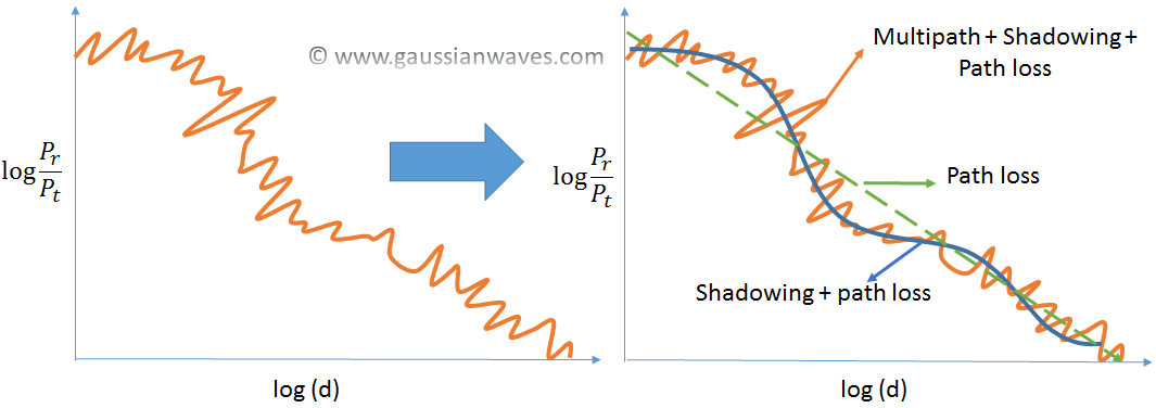
At first the signal appears very random. Upon closer look we can break it down into three main components as shown in the right half of the plot [Goldsmith2005].
1) Propagation Path Loss
2) Shadowing or slow fading
3) Multipath fading
Propagation Path Loss:
Path loss modeling is used to model following scenarios:
* Predict the signal loss between the transmitter and the receiver when a clear unobstructed path exist between them.
*Used to model the attenuation effect by various environments as the receiver and transmitted are separated by a distance.
The clear unobstructed path between the transmitter and the receiver is called Line Of Sight (LOS) path.
The most important modeling methods available for path loss modelling are
* Friis Free Space Propagation Model – models path loss
* Log Distance Path Loss or Log Normal Shadowing Model – models both path loss and shadowing
* Empirical models:
* Hata – Okumura Model
* COST 231 Extension to Hata Model
* COST 231-Walfish-Ikegami Model
* Erceg Model
* Stanford University Interim (SUI) Channel Models
* ITU Path Loss Models
I have discussed in detail some of the propagation models in these articles. Do check them out.
- Introduction to Large scale propagation models
- Friis free space propagation model
- Log distance path loss model
- Two ray ground reflection model
- Modeling diffraction loss
- Hata Okumura model for outdoor propagation
Shadowing :
If the environment contains objects like building and trees, some part of the transmitted signal gets affected by absorption, reflection, diffraction and scattering. This effect is called shadowing. It is also referred as slow fading or long-term fading.
Multipath fading:
A signal traveling in an environment may get reflected by several objects on the path. This gives rise to several reflected signals. The reflected signals arrive at the receiver at different time instants and with different intensities leading to multipath propagation. Depending on the phase of the each individual reflected signal, the received signal power may increase or decrease. A small variation in the phase of the each reflected signal from each multipath may lead to significant difference in the total received power. This phenomena is also referred as fast fading or short-term fading.
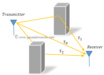
The multiple reflected copies of the transmitted signal arrive at the receiver at different time instants and at different power levels. This characteristic of the multipath phenomena is described by Power Delay Profile (PDP) as shown below. Power Delay profile gives a list of different time delays of each multipath (time delays are due to different length of the each individual reflected path) and the associated power levels.
This article discusses power delay profile in details.
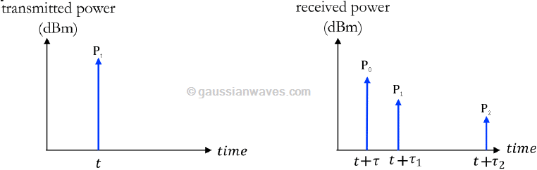
The maximum delay for which the received power level becomes negligible is called maximum delay spread τmax. Sometimes Root-Mean-Square value τrms is used instead of the maximum value.
This article discusses power delay profile in details.
Rate this article: [ratings]
Reference
[Goldsmith2005] Andrea Goldsmith, “Wireless Communications,” Cambridge University Press, 2005,644 pp.↗
Books by the author
[table “23” not found /]
This illustration of channel Modeling proved to be very helpful. it contains very basic but important concepts that may help individuals to go in deep.
Thank you for a very informative post…
Do you have an example in matlab for data transmission through fast fading channels
Hi, i am doing my m tech final year project on selectively triggered cooperative spectrum sensing in cognitive radio networks. I would like to get the matlab simulation code for spectrum sensing by energy detection at each individual sensor(Secondary User) node. somebody please help…
hi, how do you calculate Total Received Power for Multipath Propagation, is it calculating per time instant or one time period of carrier frequency signal?