Key focus: Window function smooths the observed signal over the edges. Analysis of some important parameters to help select the window for an application.
Spectral leakage
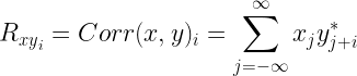
As we know, the DFT operation can be viewed as processing a signal through a set of filter banks with bandwidth Δf centered on the bin (frequency) of interest (Figure 1). To accurately resolve the frequency component in each bin, we desire the resolution bandwidth Δf to be as small as possible. In effect, each filter filter bank is viewed as filter having a brick-wall response with narrow bandwidth. If the signal under study contains several spectral components and broadband noise, the computed amplitude of the DFT output in each bin (filter bank) is significantly affected by the noise contained in the corresponding bandwidth of the filter bank.


In reality, signals are of time-limited nature and nothing can be known about the signal beyond the measured interval. When the time-limited signal slice is subjected to analysis using FFT algorithm (used for computing DFT), the FFT implicitly assumes that the signal essentially repeats itself after the observed interval. This may lead to discontinuities at the edges of each slice, that causes the energy contained in each frequency bin to spill into other bins. This phenomenon is called spectral leakage.
Equivalent Noise Bandwidth:[2]
To suppress the spectral leakage, the signals are multiplied with a window function so as to smooth the discontinuity at the edges of the FFT slices. As a result, the choice of window function affects the amount of signal and noise that goes inside each filter bank. Hence the amount of noise that gets accumulated into each filter bank is affected by the bandwidth of the chosen window function. In effect, the amplitude estimate in each frequency bin is influenced by the amount of accumulated noise contributed by the window function of choice. In other words, the noise floor displayed at the FFT output, varies according to the window of choice.
Equivalent noise bandwidth (ENBW), often specified in terms of FFT bins, is the bandwidth of a fictitious brick-wall filter such that the amount of noise power accumulated inside the brick-wall filter is same as the noise power accumulated when processing white noise through the selected window.


In discrete domain, the equivalent noise bandwidth Benbw can be computed using time domain samples as
where L is the length of the window.
ENBW is a commonly used metric to characterize the variation in the displayed noise floor if a non rectangular window is used. If noise floor measurements are desired, the ENBW correction factor need to be applied to account for the variation in the noise floor [3]. Table 1 below, lists the ENBW (bins) and ENBW correction factor for some well known window functions.
Following figure illustrates the equivalent noise bandwidth illustrated for Hann window.


Read more on Equivalent noise bandwidth…
Coherent power gain:
In time-domain, windowing a signal reduces the amplitude of the signal at its boundaries (Figure 4). This causes a reduction in the amplitude of the spectral component when FFT used to visualize the signal in frequency domain. This reduction in amplitude in the spectral components is characterized as coherent power gain (which actually is a loss). So, when FFT is computed on a windowed signal, in order to compensate for the loss in the amplitude, we simply add the coherent power gain to the FFT output.


Coherent power gain of a window w[n] of length L is given by
Following plot depicts the coherent power gain (i.e, the reduction in the FFT magnitude when the input signal is processed with a window) of a windowed sinusoidal signal of frequency 10 Hz. The length of the window is L = 151 points and the simulation assumes an oversampling factor of 16 (i.e, Fs=160 Hz). The FFT length is NFFT =2048.
Table 1 below, lists the coherent power gain for some well known window functions.


Scalloping loss
As discussed above, the FFT (equivalently the DFT) operation can be seen as processing a signal through a set of filter banks with bandwidth Δf centered on the successive bin frequencies. The frequency resolution (Δf) of FFT depends on the size of FFT (NFFT) and the sampling frequency Fs.
Therefore, the FFT process can measure amplitude of tones that are multiples of the frequency resolution Δf. That is, if the frequency of the observed signal matches a particular bin frequency, the signal amplitude will be maximum at that bin.
However, if the tone of the signal falls between two bins, the signal power is spread between the adjacent bins and hence the displayed signal amplitude/power is reduced.
Scalloping loss quantifies the worst case reduction in the signal level, when the tone of the observed signal falls exactly mid way between two bin frequencies. The worst case scalloping loss is calculated as
In reality, scalloping loss depends on the type of window and the relationship between the signal tones to the bin frequencies. Table 1 below, lists the scalloping loss for some well known window functions.


Figure of merits for window functions


List of window functions
Boxcar (Rectangular)


Barthann


Bartlett

Blackman


Blackman-Harris

Bohman

Cosine

Flattop


Hamming


Hann

Nuttall


Parzen

Triangular


Rate this article: Note: There is a rating embedded within this post, please visit this post to rate it.
References:
[1] Harris, “On the Use of Windows for Harmonic Analysis with the Discrete Fourier Transform”, proceedings of IEEE, vol. 66, no. 1, January 1978.↗
[2] Stefan Scholl, “Exact Signal Measurements using FFT Analysis”,Microelectronic Systems Design Research Group, TU Kaiserslautern, Germany.↗
Similar articles
[1] Understanding Fourier Series
[2] Introduction to digital filter design
[3] Design FIR filter to reject unwanted frequencies
[4] FIR or IIR ? Understand the design perspective
[5] How to Interpret FFT results – complex DFT, frequency bins and FFTShift
[6] How to interpret FFT results – obtaining magnitude and phase information
[7] Analytic signal, Hilbert Transform and FFT
[8] FFT and spectral leakage
[9] Moving average filter in Python and Matlab
[10] Window functions – figure of merits
[11] Equivalent noise bandwidth (ENBW) of window functions
Additional Resources:
[1] If you are particularly interested in calculating the Equivalent Noise Bandwidth of Analog Filters refer – Thomas J. Karras,”Equivalent Noise Bandwidth Analysis from Transfer Functions”,NASA Technical Note,NASA TN D-2842.↗
[2] Strategies for Choosing Windows : Michael Cerna and Audrey F. Harvey,”The Fundamentals of FFT-Based Signal Analysis and Measurement”,National Instruments Application Notes 041.↗
Books by the author
 Wireless Communication Systems in Matlab Second Edition(PDF) Note: There is a rating embedded within this post, please visit this post to rate it. |  Digital Modulations using Python (PDF ebook) Note: There is a rating embedded within this post, please visit this post to rate it. |  Digital Modulations using Matlab (PDF ebook) Note: There is a rating embedded within this post, please visit this post to rate it. |
| Hand-picked Best books on Communication Engineering Best books on Signal Processing |
||


![x(t) = a(t) cos \left[ \phi (t) \right]](https://s0.wp.com/latex.php?latex=x%28t%29+%3D+a%28t%29+cos+%5Cleft%5B+%5Cphi+%28t%29+%5Cright%5D+&bg=ffffff&fg=000&s=0&c=20201002)


![z(t) = z_r(t) + j z_i(t) = x(t) + j HT \left[ x(t) \right]](https://s0.wp.com/latex.php?latex=z%28t%29+%3D+z_r%28t%29+%2B+j+z_i%28t%29+%3D+x%28t%29+%2B+j+HT+%5Cleft%5B+x%28t%29+%5Cright%5D+&bg=ffffff&fg=000&s=2&c=20201002)


![\phi(t) = \angle z(t) = arctan \left[ \frac{z_i(t)}{z_r(t)} \right]](https://s0.wp.com/latex.php?latex=%5Cphi%28t%29+%3D+%5Cangle+z%28t%29+%3D+arctan+%5Cleft%5B+%5Cfrac%7Bz_i%28t%29%7D%7Bz_r%28t%29%7D+%5Cright%5D+&bg=ffffff&fg=000&s=2&c=20201002)


![cos[\phi(t)]](https://s0.wp.com/latex.php?latex=cos%5B%5Cphi%28t%29%5D&bg=ffffff&fg=000&s=0&c=20201002)


![x[n]](https://s0.wp.com/latex.php?latex=x%5Bn%5D&bg=ffffff&fg=000&s=0&c=20201002)
![x[n] = x(nT)](https://s0.wp.com/latex.php?latex=x%5Bn%5D+%3D+x%28nT%29+&bg=ffffff&fg=000&s=0&c=20201002)

![X(f) = \displaystyle{ T \sum_{n=0}^{N-1} x[n] e^{-j 2 \pi f n T} }\quad (6)](https://s0.wp.com/latex.php?latex=X%28f%29+%3D+%5Cdisplaystyle%7B+T+%5Csum_%7Bn%3D0%7D%5E%7BN-1%7D+x%5Bn%5D+e%5E%7B-j+2+%5Cpi+f+n+T%7D+%7D%5Cquad+%286%29+%C2%A0&bg=ffffff&fg=000&s=2&c=20201002)

![(a) CTFT of continuous signal x(t), (b) Spectrum of x[n] resulted due to periodic sampling and (c) Periodic one-sided spectrum of analytical signal z[n]](https://i0.wp.com/www.gaussianwaves.com/gaussianwaves/wp-content/uploads/2017/04/discrete_time_analytic_signal_PNG.png?resize=594%2C494&ssl=1)
![z[n]](https://s0.wp.com/latex.php?latex=z%5Bn%5D&bg=ffffff&fg=000&s=0&c=20201002)
![z[n] = z_r[n] + j z_i[n]](https://s0.wp.com/latex.php?latex=z%5Bn%5D+%3D+z_r%5Bn%5D+%2B+j+z_i%5Bn%5D&bg=ffffff&fg=000&s=0&c=20201002)

![z_r[n] = x[n]](https://s0.wp.com/latex.php?latex=z_r%5Bn%5D+%3D+x%5Bn%5D&bg=ffffff&fg=000&s=0&c=20201002)

![\displaystyle{ \sum_{n=0}^{N-1} z_r[n] z_i[n] = 0 }](https://s0.wp.com/latex.php?latex=%5Cdisplaystyle%7B+%5Csum_%7Bn%3D0%7D%5E%7BN-1%7D+z_r%5Bn%5D+z_i%5Bn%5D+%3D+0+%7D++&bg=ffffff&fg=000&s=2&c=20201002)


![Z[m]](https://s0.wp.com/latex.php?latex=Z%5Bm%5D&bg=ffffff&fg=000&s=0&c=20201002)

![z[n] = \displaystyle{ \frac{1}{NT} \sum_{m=0}^{N-1} z[m] \; exp \left( j 2 \pi mn/N\right)}](https://s0.wp.com/latex.php?latex=z%5Bn%5D+%3D+%5Cdisplaystyle%7B+%5Cfrac%7B1%7D%7BNT%7D+%5Csum_%7Bm%3D0%7D%5E%7BN-1%7D+z%5Bm%5D+%5C%3B+exp+%5Cleft%28+j+2+%5Cpi+mn%2FN%5Cright%29%7D+&bg=ffffff&fg=000&s=2&c=20201002)